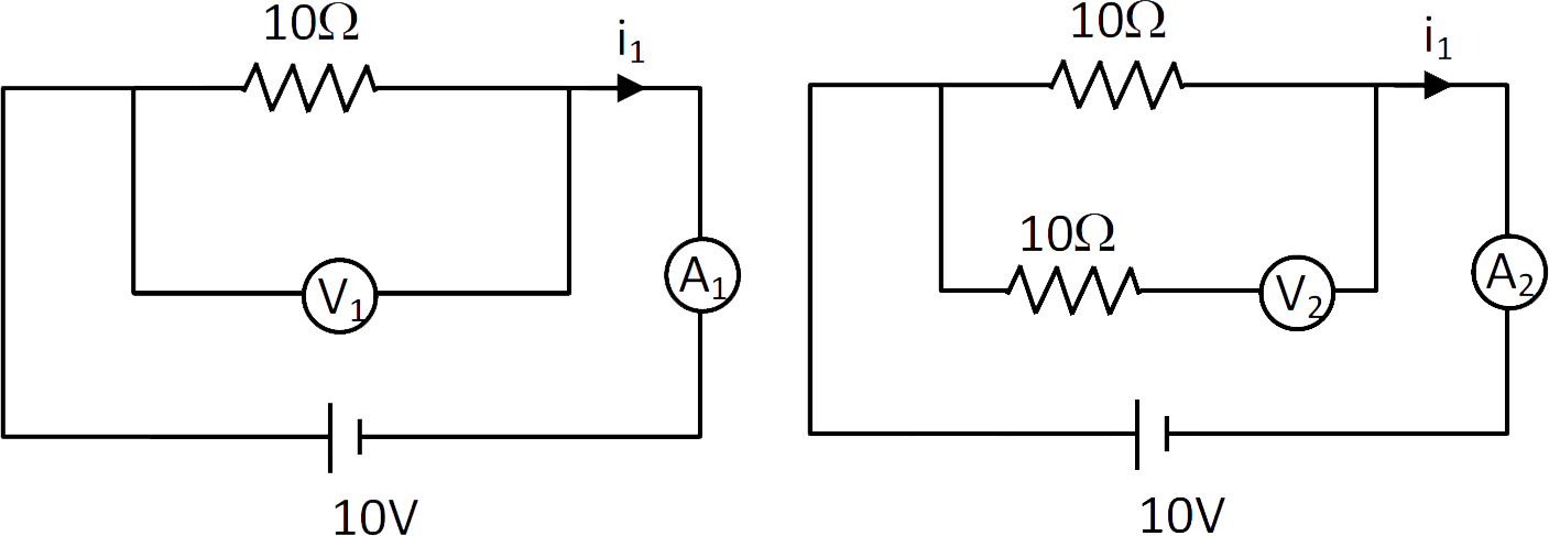
In the circuits shown below, the readings of the voltmeters and ammeters will be:

A
V2>V1andi1>i2
B
V2>V1andi1=i2
C
V1=V2andi1>i2
D
V1=V2andi1=i2
Text Solution
The correct Answer is:D
We know that resistance of ideal voltmeter is infinite. We can assume branch of voltmeter without current. In second circuit also net resistance of branch of voltmeter remains infinite because adding one more resistance of 10Ω along with voltmeter of infinite resistance makes no difference. Hence both the circuits are same Moreover ideal ammeter has zero resistance. Hence equivalent resistance of both the circuits is equal to 10Ω.
I1=I2=10/10=1A
V1=V2=1×10=10V Hence option (d) is correct
|
Topper's Solved these Questions
- CURRENT ELECTRICITYBOOK - MODERN PUBLICATIONCHAPTER - CURRENT ELECTRICITYEXERCISE - Objective Type Questions (MULTIPLE CHOICE QUESTIONS) (B. MULTIPLE CHOICE QUESTION JEE (MAIN) & OTHER STATE BOARDS FOR ENGINEERING ENTRANCE)
45 Videos
- CURRENT ELECTRICITYBOOK - MODERN PUBLICATIONCHAPTER - CURRENT ELECTRICITYEXERCISE - Objective Type Questions (MULTIPLE CHOICE QUESTIONS) (B. MULTIPLE CHOICE QUESTION JEE (ADVANCED) FOR IIT ENTRANCE)
9 Videos
- CURRENT ELECTRICITYBOOK - MODERN PUBLICATIONCHAPTER - CURRENT ELECTRICITYEXERCISE - Objective Type Questions (MULTIPLE CHOICE QUESTIONS) (A. MULTIPLE CHOICE QUESTIONS WITH ONLY ONE CORRECT ANSWER)
36 Videos
- ATOMS BOOK - MODERN PUBLICATIONCHAPTER - ATOMS EXERCISE - Chapter Practice Test
16 Videos
- DUAL NATURE OF RADIATION AND MATTER BOOK - MODERN PUBLICATIONCHAPTER - DUAL NATURE OF RADIATION AND MATTER EXERCISE - CHAPTER PRACTICE TEST
15 Videos
Similar Questions
Knowledge Check
In the circuits shown below, the readings of the voltmeters and the ammeters will be:
 AV2>V1 and i1>i2BV2>V1 and i1=i2CV1=V2 and i1>i2DV1=V2 and i1=i2
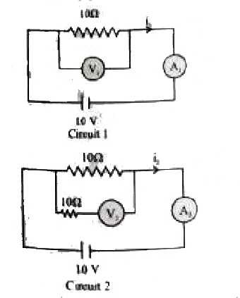
In the circuits shown below, the readings of the voltmeters and the ammeters will be
 AV2>V1andi1=i2BV1=V2andi1>i2Cv1=V2andi1=i2DV2>V1andi1>i2
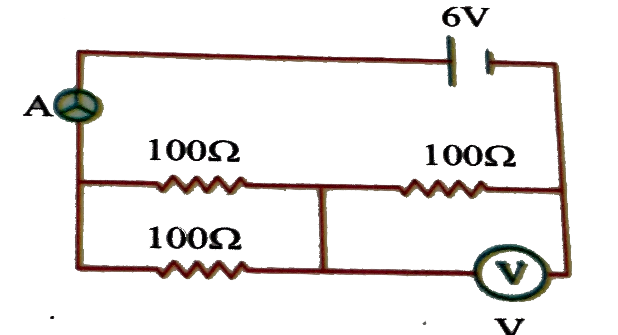
In the circuit shown, the reading of the voltmeter and the ammeter areA4V.0.2AB2V,0.4AC3V,0.6AD4V,0.04A
In the circuit shown below. The reading of the voltmeter V is

View SolutionIn the circuit shown below what will be the reading of the voltmeters and ammeter?
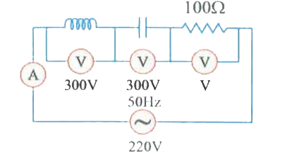
View SolutionIn the circuit shown below what will be the reading of the voltmeters and ammeter?

View SolutionIn the circuit shown below, what will be the reading of the voltmeter and ammeter?
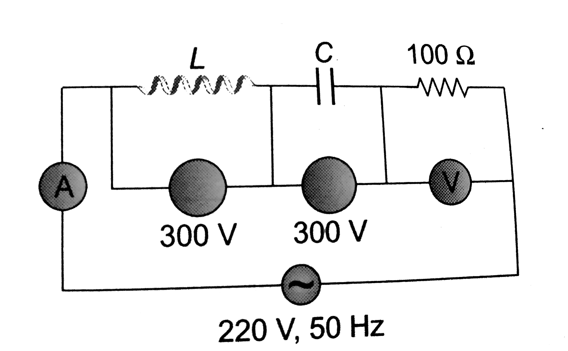
View SolutionIn the circuit shown below, what will be the reading of the voltmeter and ammeter?

View Solution
