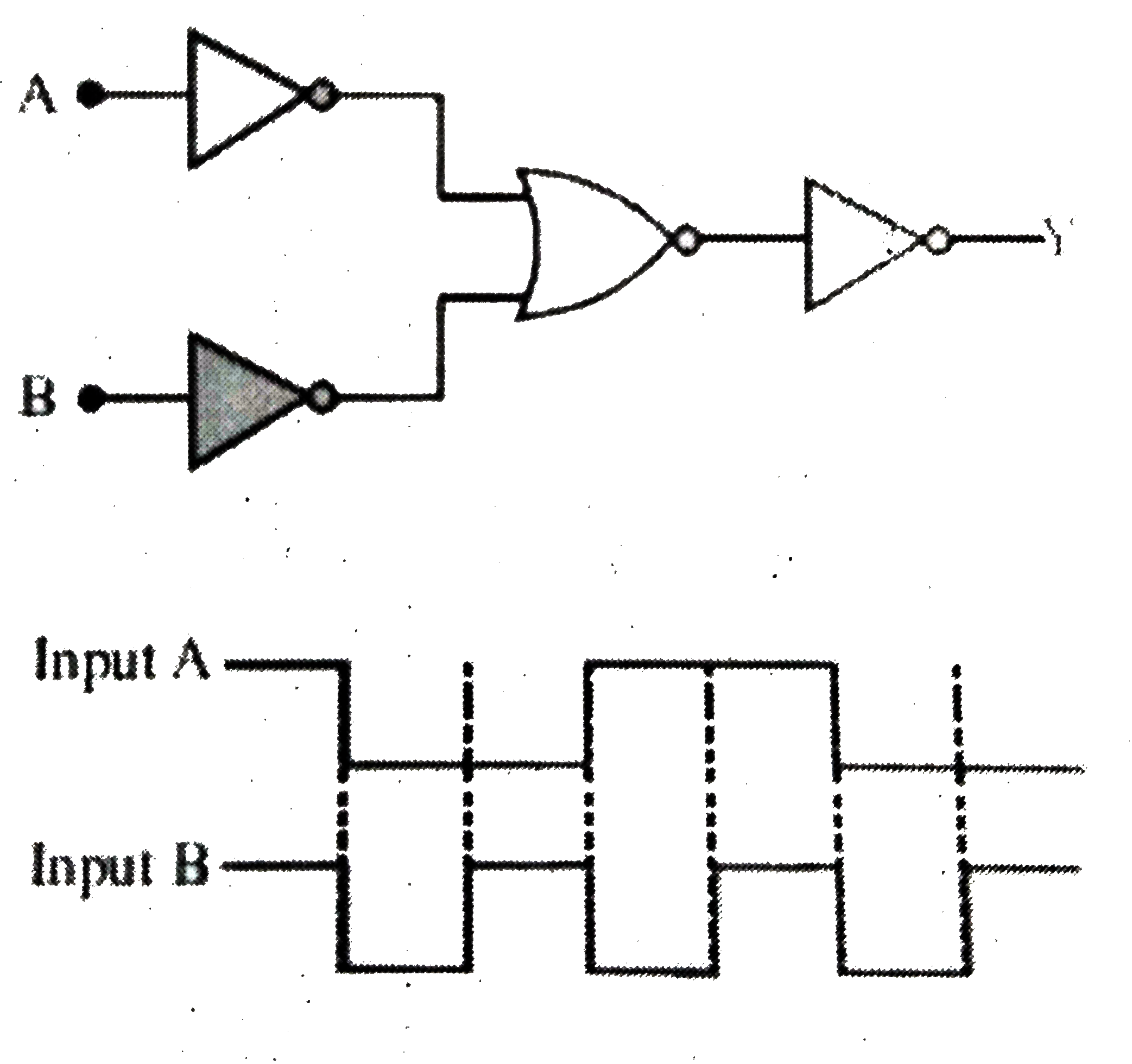
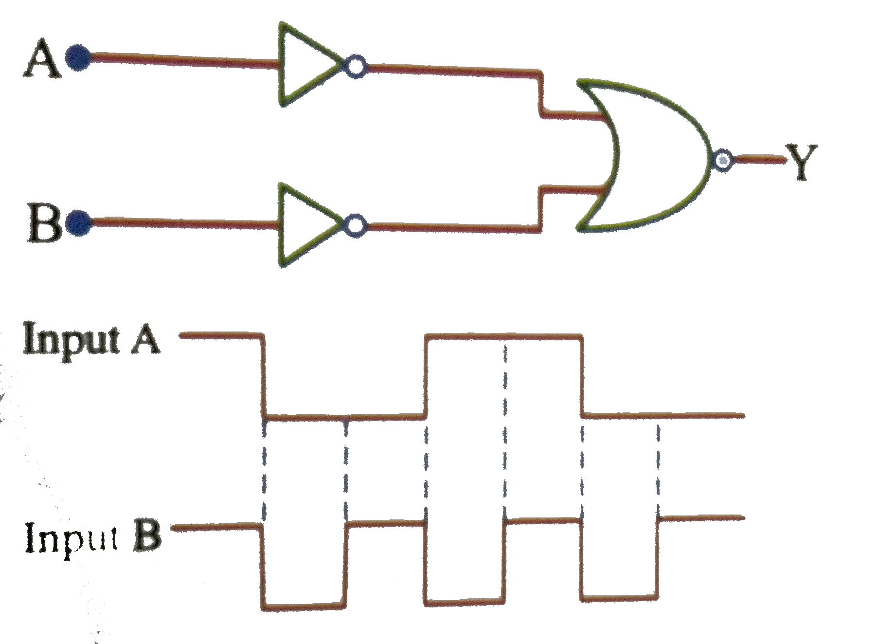
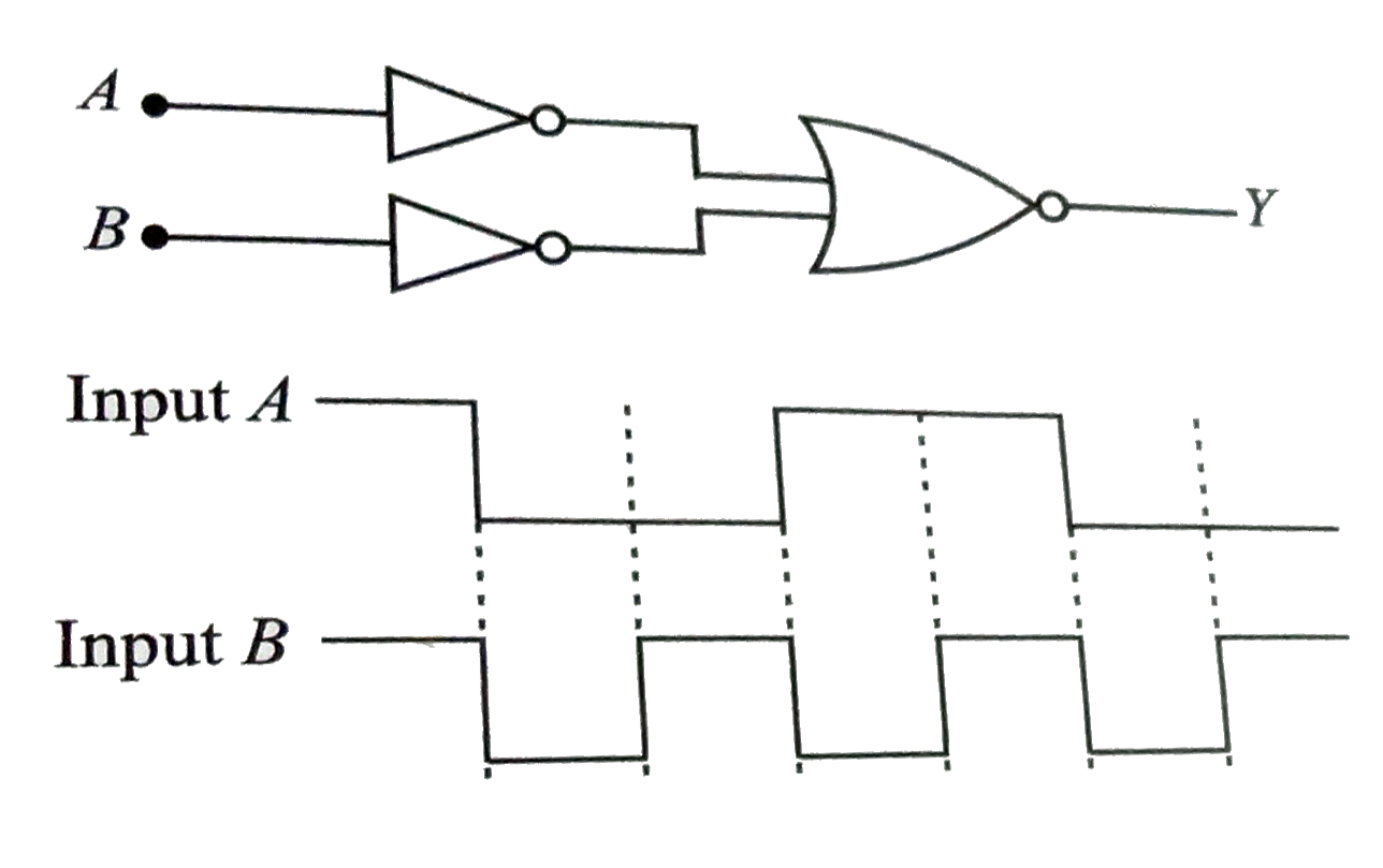
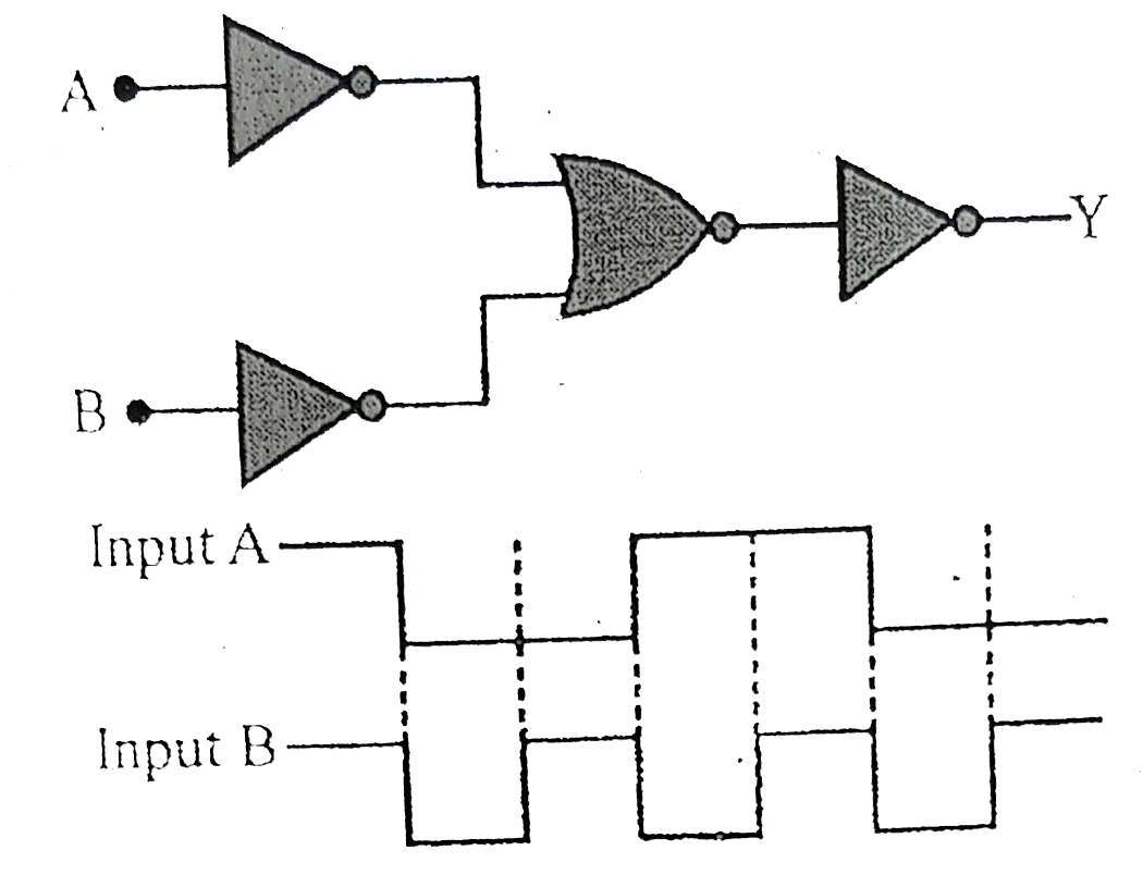
The logic circuit shown below has the input waveforms 'A' and 'B' as shown. Pick out the correct output waveform
 .
.
A

B

C

D

Video Solution
Text Solution
The correct Answer is:A

The output of the circuit is
Y=¯¯¯¯¯¯¯¯¯¯¯¯¯¯¯A+¯¯¯B=¯¯¯¯¯¯¯A.¯¯¯¯¯¯B=A.B (By de Morgan.s theorem)
It is the Boolean expression of AND gate.
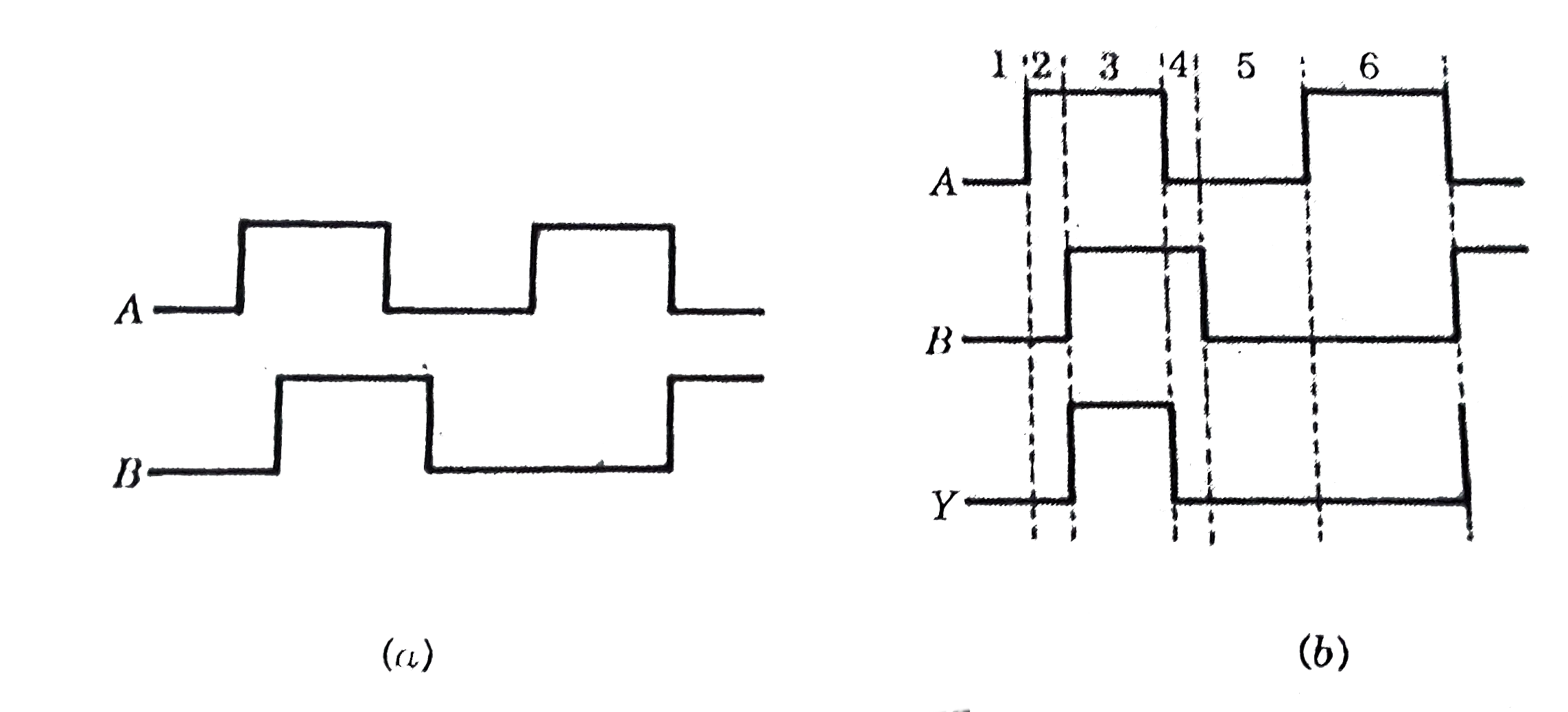
The output waveform corresponding to given input waveforms A and B is as shown below.

|
Topper's Solved these Questions
- SOLID STATE ELECTRONS BOOK - MTG-WBJEECHAPTER - SOLID STATE ELECTRONS EXERCISE - WB JEE WORKOUT (CATEGORY 3 : One or More than one option Correct Type)
10 Videos
- SOLID STATE ELECTRONS BOOK - MTG-WBJEECHAPTER - SOLID STATE ELECTRONS EXERCISE - WB JEE Previous Years Questions (CATEGORY 1 : Single Option Correct Type)
15 Videos
- SOLID STATE ELECTRONS BOOK - MTG-WBJEECHAPTER - SOLID STATE ELECTRONS EXERCISE - WB JEE Previous Years Questions (CATEGORY 1 : Single Option Correct Type)
15 Videos
- PARTICLE NATURE OF LIGHT AND WAVE PARTICLE DUALISMBOOK - MTG-WBJEECHAPTER - PARTICLE NATURE OF LIGHT AND WAVE PARTICLE DUALISMEXERCISE - WB JEE PREVIOUS YEARS QUESTIONS
15 Videos
- THERMODYNAMICSBOOK - MTG-WBJEECHAPTER - THERMODYNAMICSEXERCISE - WB JEE Previous Years Questions
12 Videos
Similar Questions
Knowledge Check
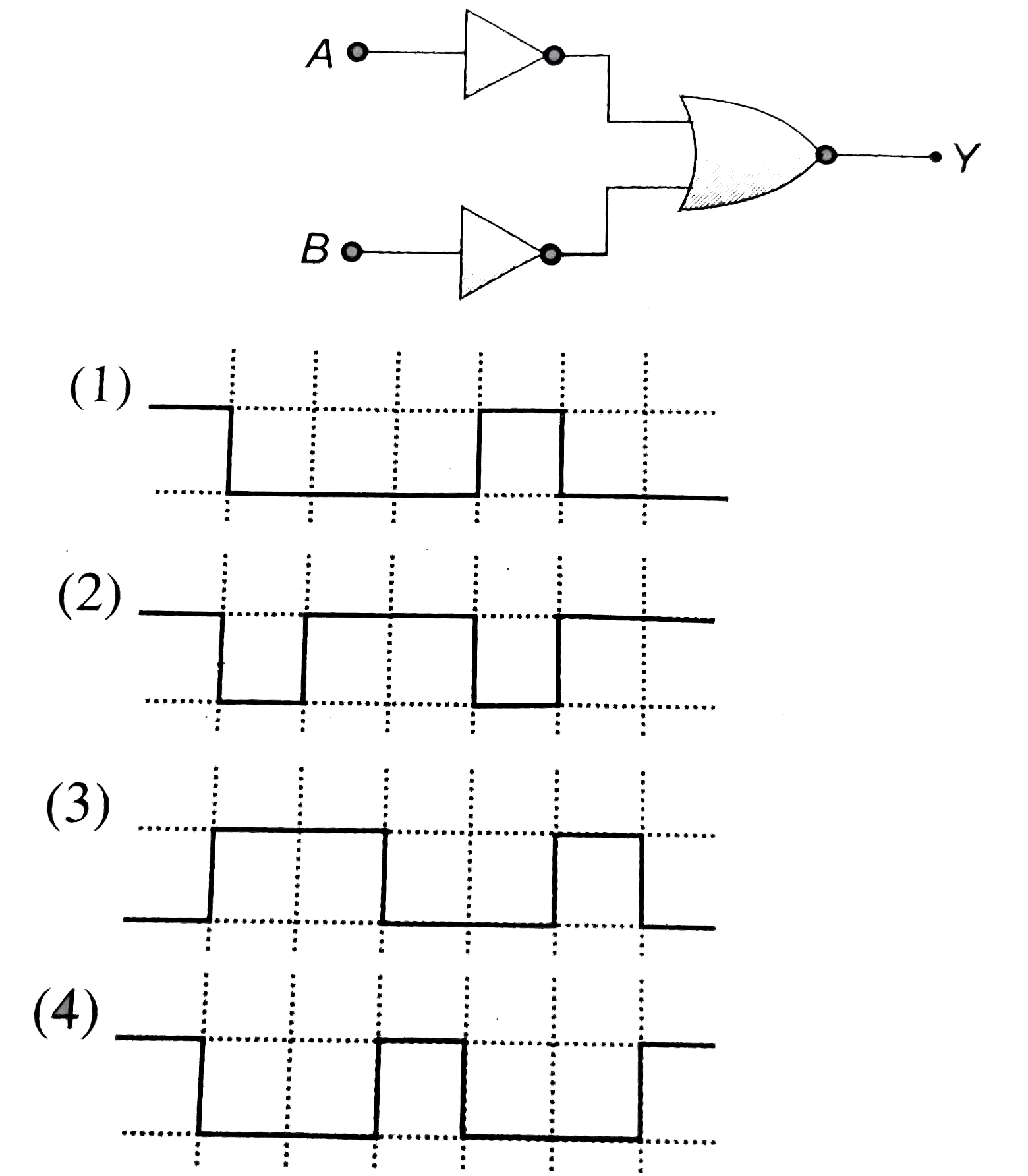
The logic circuit shown belows has the input waveforms 'A' and 'B' as shown. Pick out the correct output waveform
 A
A B
B C
C D
D
The logic circuit shown below has the input waveform 'A' and 'B' as shown. Pick out the correct output waveform
_E01_490_Q01.png)
Output is :-A_E01_490_O01.png) B
B_E01_490_O02.png) C
C_E01_490_O03.png) D
D_E01_490_O04.png)
The logic circuit shown below has the inputs waveforms A and B as shown. Pick out the correct output waveform.
 A
A B
B C
C D
D
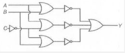
The output Y for logic diagram shown below is
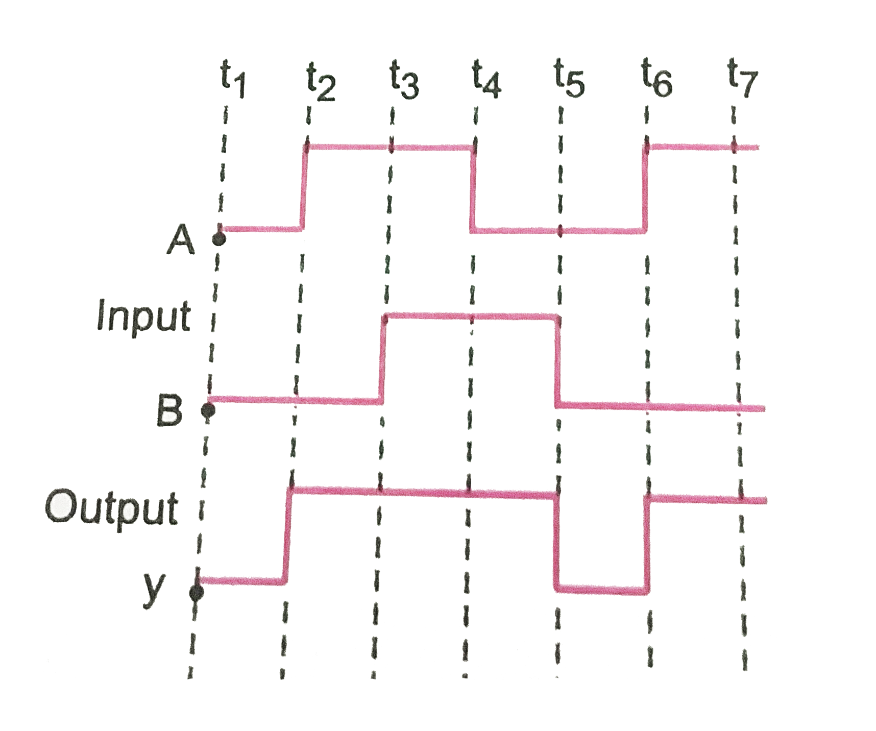
View SolutionThe Fig shown input waveforms A and B to a logic gate. Draw the output waveform for an OR gate. Write the truth table for this logic gate and draw its logic symbol.
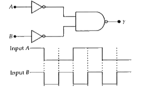
View SolutionThe logic circuit shown below has the input waveforms A and B as shown. Pick out the correct out put waveform.
View SolutionThe logic circuit shown has the input waveforms 'A' and 'B' as shown. Pick out the CORRECT output waveform:-
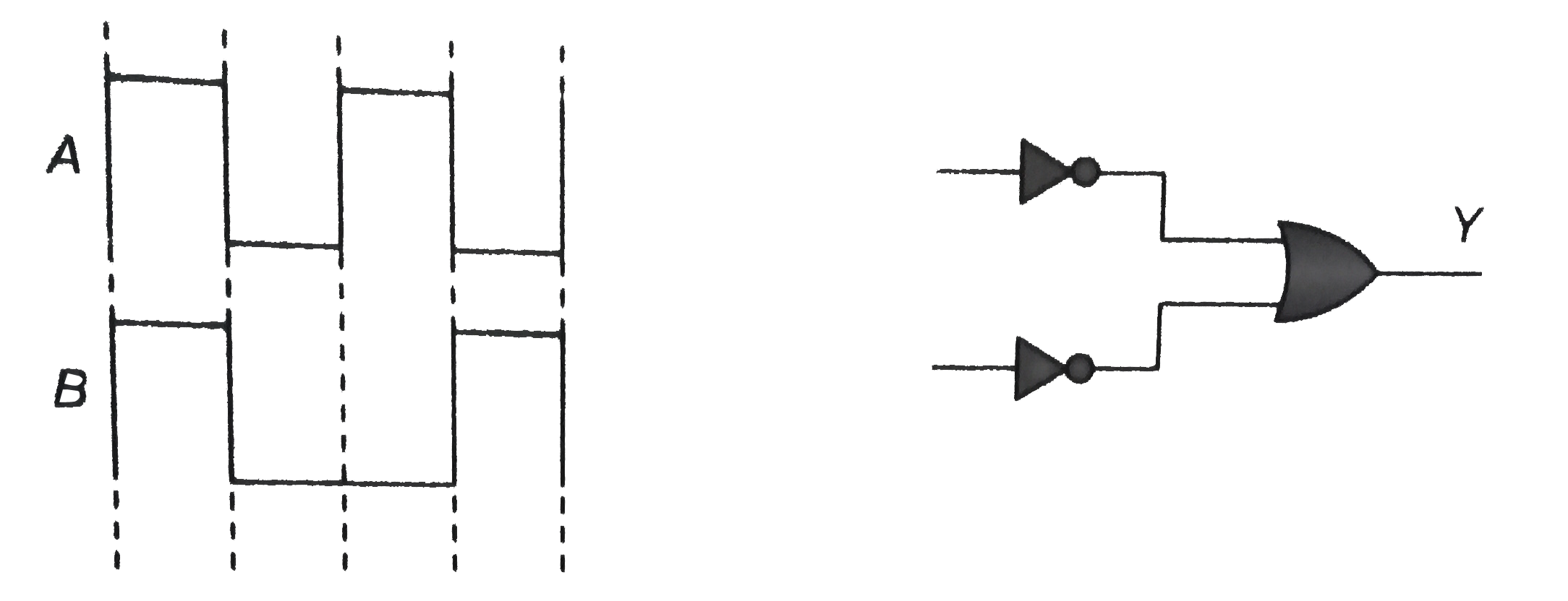
View SolutionIn the given circuit as shown the two input waveform A and B are applied simultaneously. The resultant waveform Y is
View Solution

