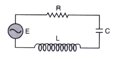
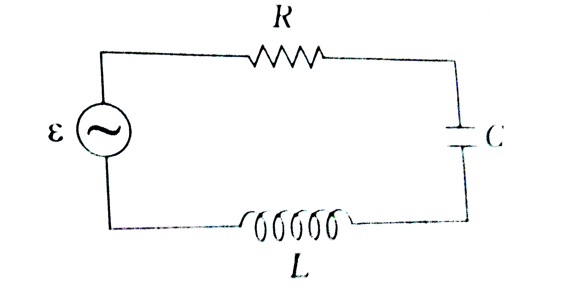
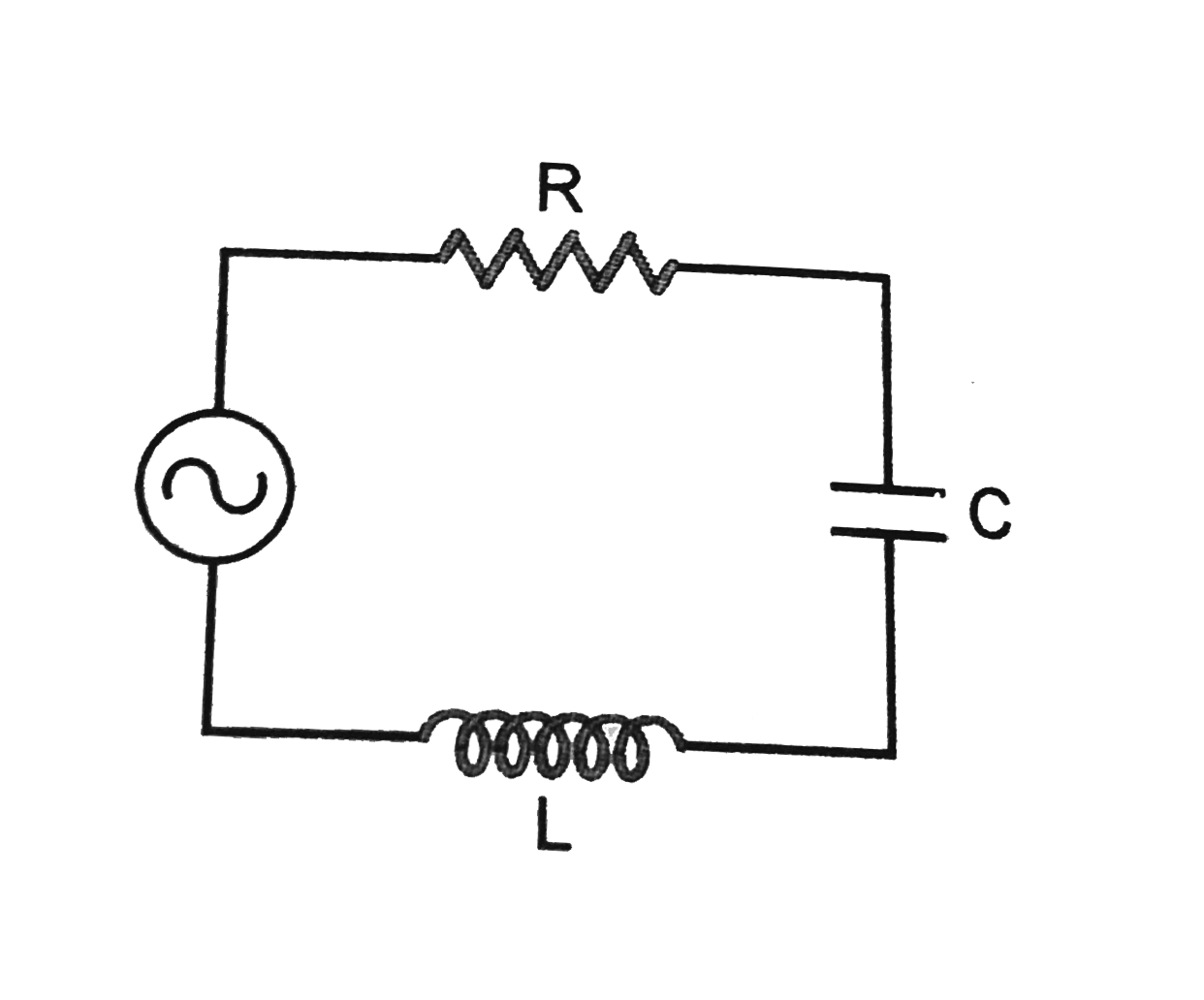
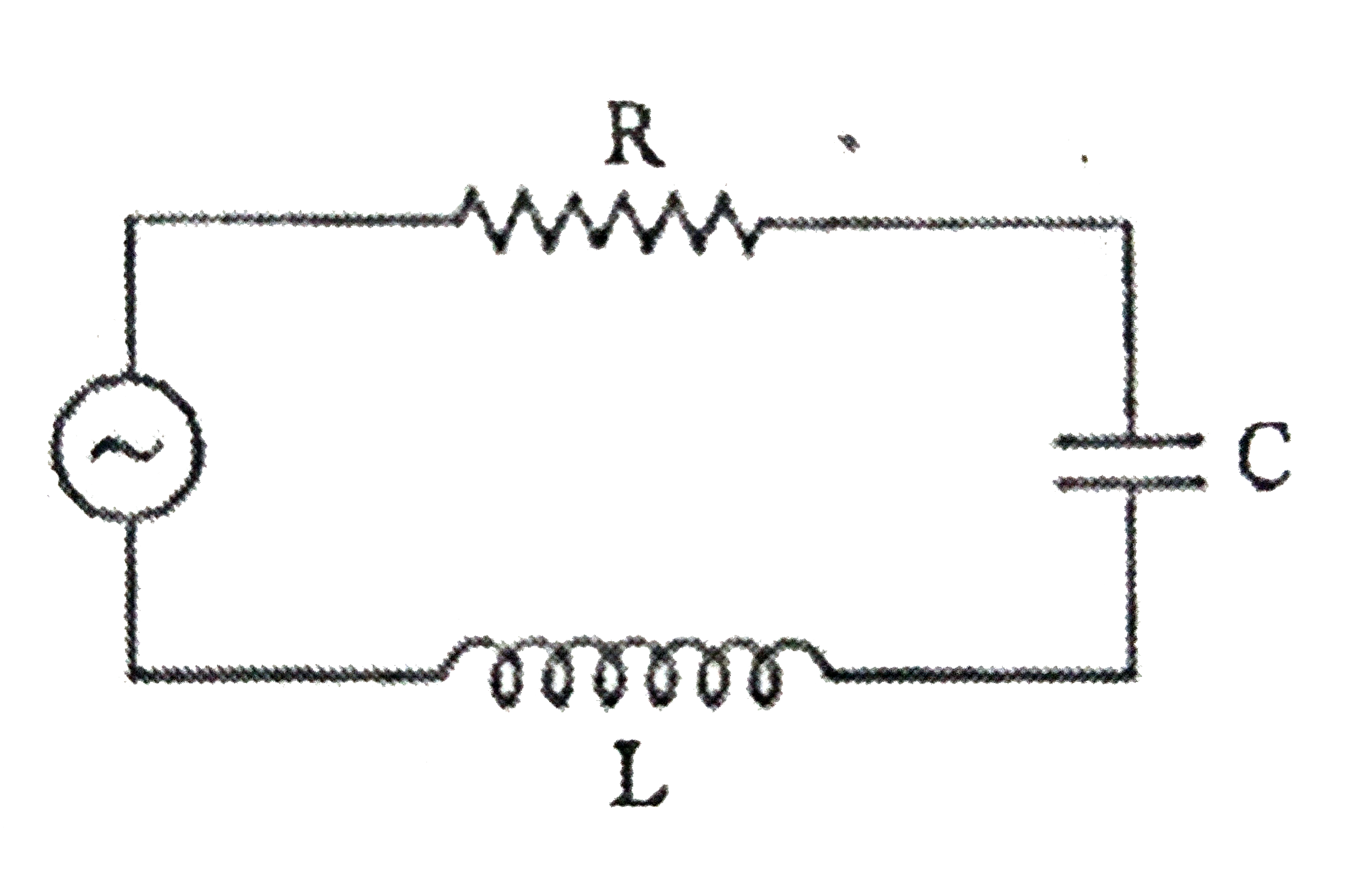
The figure shows a series LCR circuit connected to a variable frequency of 220 V source with L = 50 mH, C=80μF and R=40Ω.
(i) The source frequency which drives the circuit in resonance,
(ii) the quality factor Q of the circuit.

(i) ω0=1√LC
=1√50×10−3×80×10−6=500rad/s
Alternatively,
v=5002π=250πHz≈80Hz
(ii) Q=ω0LR
=500×50×10−340
= 0.625
Topper's Solved these Questions
- ALTERNATING CURRENTBOOK - OSWAAL PUBLICATIONCHAPTER - ALTERNATING CURRENTEXERCISE - Topic - 2 (Short Answer Type Questions -II)
7 Videos
- ALTERNATING CURRENTBOOK - OSWAAL PUBLICATIONCHAPTER - ALTERNATING CURRENTEXERCISE - Topic - 2 (Long answer Type Questions)
4 Videos
- ALTERNATING CURRENTBOOK - OSWAAL PUBLICATIONCHAPTER - ALTERNATING CURRENTEXERCISE - Topic -2 (Very Short Answer Type Questions)
4 Videos
- 2020 Solved Paper I BOOK - OSWAAL PUBLICATIONCHAPTER - 2020 Solved Paper I EXERCISE - Exercise
41 Videos
- ATOMSBOOK - OSWAAL PUBLICATIONCHAPTER - ATOMSEXERCISE - NUMERICAL PROBLEMS
11 Videos
Similar Questions
The figure shows a series LCR circuit connected to a varriable of 200 V source with L=50 mH, C=80μF and R=40Ω find.
(i) the source frequency which drives the circuit in resonance,
(ii) the quality factor (Q) of the circuit.

View SolutionFigure here, shows a series L-C-R circuit connected to a variable frequency 230 V source. L = 5.0H, C = 80μF and r =40Ω
(a) Determine the source frequency which drives the circuit in resonance.
(b) Obtain the impedance of the circuit and the amplitude of current at the resonating frequency.
(c) Determine the rms potential drops across the three elements of the circuit. show that the potential drop across the L-C combination is zero at the resonating frequency.

View Solution
Knowledge Check
Figure shows a series LCR circuit connected to a variable frequency 230 V source.

The source frequency which drives the circuit the circuit in resonance isA4 HzB5 HzC6 HzD8 HzFigure shows a series LCR circuit connected to a variable frequency 230 V source.

The source frequency which drives the circuit the circuit in resonance isA4 HzB5 HzC6 HzD8 Hz
Figure here, shows a series L-C-R circuit connected to a variable frequency 230 V source. L = 5.0H, C = 80μF and r =40Ω
(a) Determine the source frequency which drives the circuit in resonance.
(b) Obtain the impedance of the circuit and the amplitude of current at the resonating frequency.
(c) Determine the rms potential drops across the three elements of the circuit. show that the potential drop across the L-C combination is zero at the resonating frequency.

View SolutionA series LCR circuit connected to a variable frequency 230 V source has L = 5.0 H, C=80μF, R=40Ω, Fig.
(a) Determine the source frequency which drives the circuit in resonance.
(b) Obtain the impedance of the circuit and amplitude of current at at resonating frequency.
(c ) Determine the r.m.s. potential drops acorss the three elements the circuits. Show that the potential drop acorss the LC combination is zero at the resonating frequecny.

View SolutionA series LCR circuit with L=80mH,C=50μF and R=60ohm is connected to a variable frequency 220 V source. Determine (i) the source frequency which drives the circuitin resonance (iii) the quality factor Q of the circuit.
View SolutionThe figure shows a series LCR circuit with L=10.0H2,C=40μF,R=60Ω connected to a variable frequency 240 V source. Calculate
(i) The angular frequency of the source which drives the circuit at resonance.
(ii) The current at the resonating frequency.
(iii) The rms potential drop across the capacitor at resonance.

View Solution
