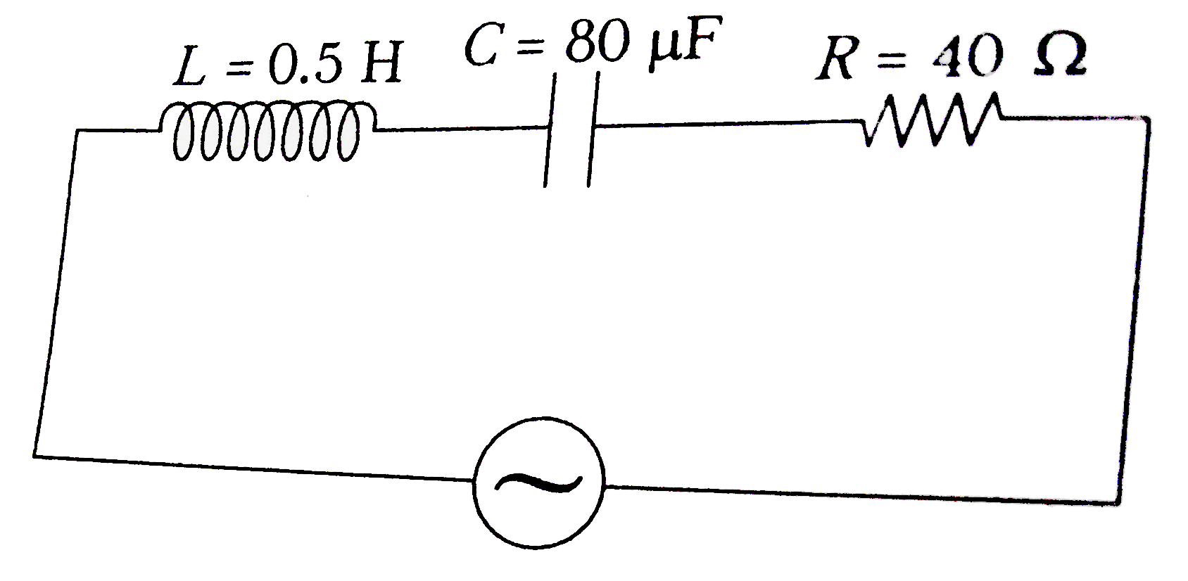
A series LCR circuit connected to a variable frequency 230 V source has L = 5.0 H, C=80μF, R=40Ω, Fig.
(a) Determine the source frequency which drives the circuit in resonance.
(b) Obtain the impedance of the circuit and amplitude of current at at resonating frequency.
(c ) Determine the r.m.s. potential drops acorss the three elements the circuits. Show that the potential drop acorss the LC combination is zero at the resonating frequecny.
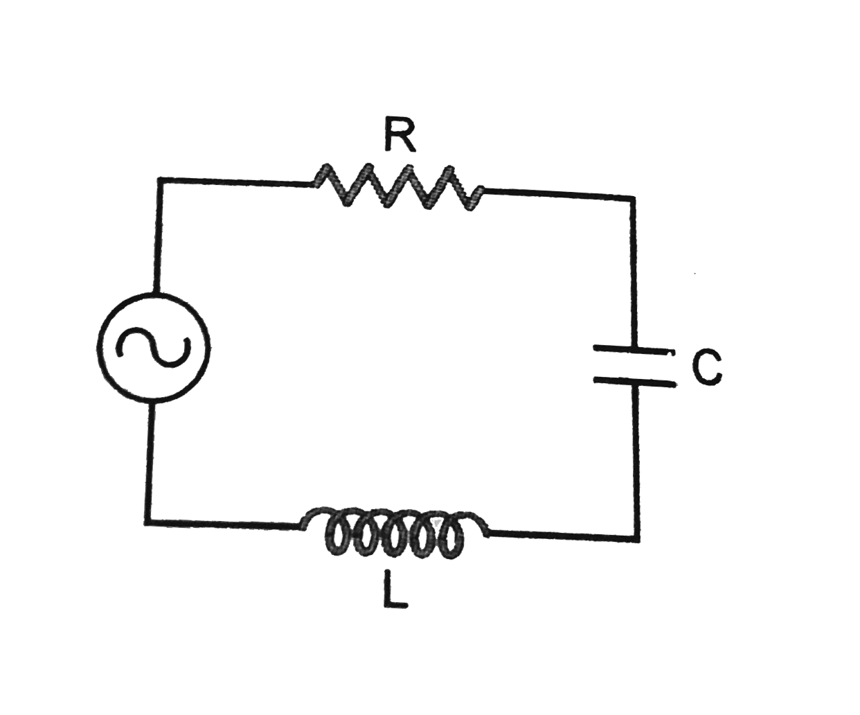
Inductance of the inductor,L=5.0H
Capacitance of the capacitor, C=80μH=80×10−6F
Resistance of the resistor, R=40Ω
Potential of the variable voltage source, V=230V
(a) Resonance angular frequency is given as:
ωR=1√LC
=1√5×80×10−6=10320=50rad/s
Hence, the circuit will come in resonance for a source frequency of 50 rad/s.
(b) Impedanc of the circuit is given by the relation,
Z=√R2+(ωL−1ωC)2
At resonance,
ωL=1ωC
∴Z=R40Ω
Amplitude of the current at the resonating frequency is given as I0=V0Z
where,
v0= Peak voltage
=√2V
∴I0=√2VZ
=√2×23040=8.13A
Hence, at resonance, the impedance of the circuit is 40 Ω and the amplitude of the current is 8.13A.
(c) RMS potential drop cross the inductor,
(VL)rms=I×ωRL
Whre,
I=rms current
=I0√2=√2V√2Z=23040A
∴(VL)rms=23040×50×5=1437.5V
Potential drop across the capacitor,
Vc)Rms=l×LωRC
=23040×150×80×10−6=1437.5V
Potential drop across the resistor.
(VR)rms=IR
23040×40=230V
Potential drop across the LC combination,
VLC=I(ωRL−1ωRC) ltbgt At resonance, (ωRL−1ωRC)
∴VLC=0
Hence, it is proved that the potential drop across the LC combination is zero zt resonating frequency.
Topper's Solved these Questions
Similar Questions
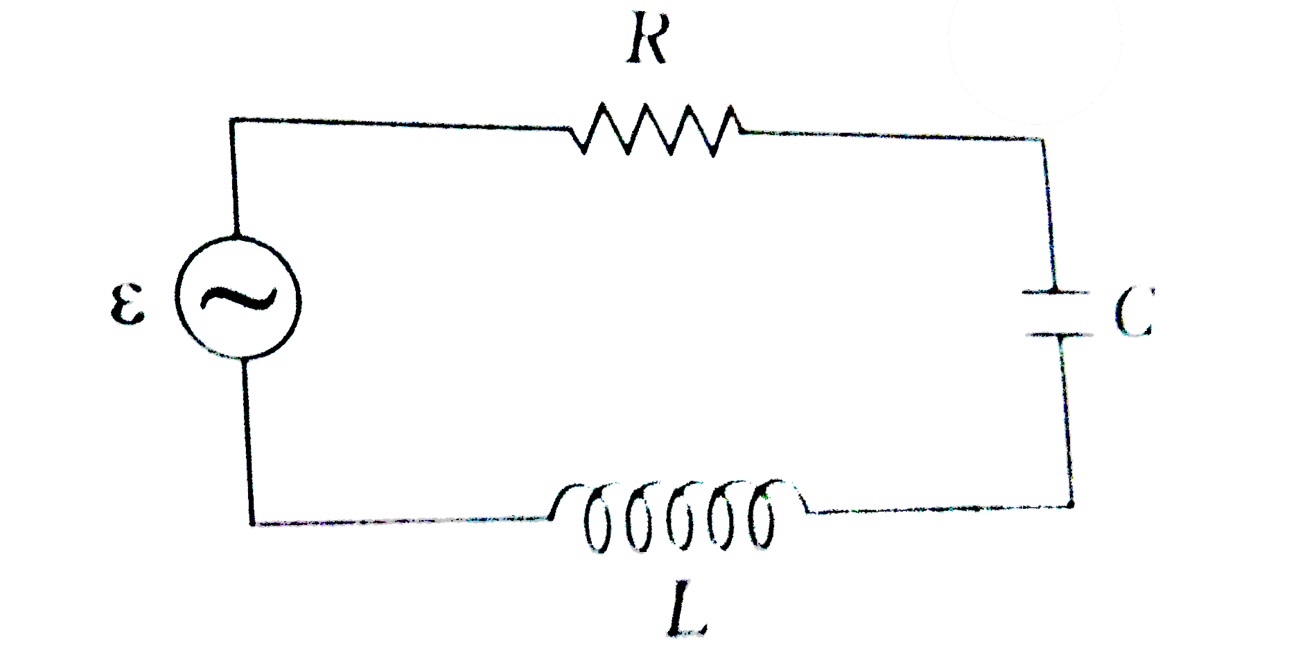
Figure here, shows a series L-C-R circuit connected to a variable frequency 230 V source. L = 5.0H, C = 80μF and r =40Ω
(a) Determine the source frequency which drives the circuit in resonance.
(b) Obtain the impedance of the circuit and the amplitude of current at the resonating frequency.
(c) Determine the rms potential drops across the three elements of the circuit. show that the potential drop across the L-C combination is zero at the resonating frequency.
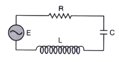
View SolutionThe figure shows a series LCR circuit connected to a varriable of 200 V source with L=50 mH, C=80μF and R=40Ω find.
(i) the source frequency which drives the circuit in resonance,
(ii) the quality factor (Q) of the circuit.
View Solution
Knowledge Check
At resonance frequency the impedance in series LCR circuit is
AmaximumBminimumCzeroDinfinityFigure shows a series LCR circuit connected to a variable frequency 230 V source.

The source frequency which drives the circuit the circuit in resonance isA4 HzB5 HzC6 HzD8 Hz
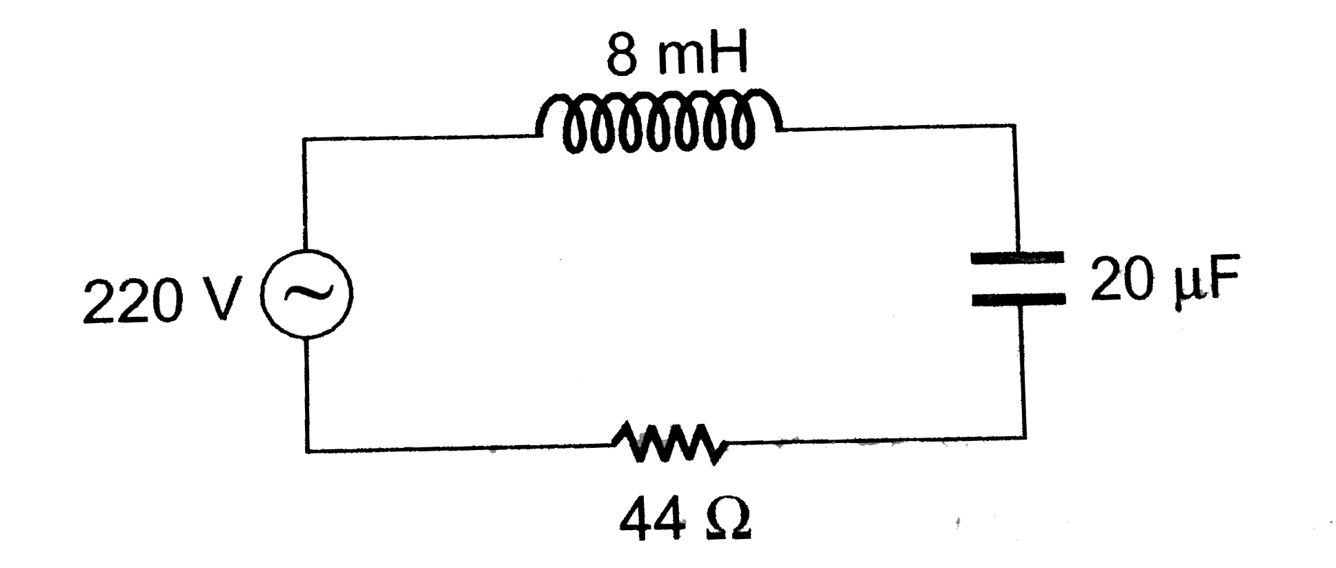
For the series LCR circuit shown in the figure, what is the resonance frequency and the amplitude of the current at the resonating frequency

View SolutionFor the series LCR circuit shown in the figure, what is the resonance frequency and the amplitude of the current at the resonating frequency
View SolutionA series L-C-R circuit is operated at resonance . Then
View SolutionIn an L-C-R series, AC circuit at resonance
View SolutionIn the given figure , a series L-C-R circuit is connected to a variable frequency source of 230 V . The impedance and amplitude of the current at the resonating frequency will be
View SolutionA series LCR circuit with L=4.0H,C=100μF and R=60Ω is connected to a variable frequency 240 V source. Calculate
(i) angular frequency of the source which drives the circuit in resonance,
(ii) current at the resonating frequency,
(iii) rms potential drop across the inductance at resonance.
View Solution
