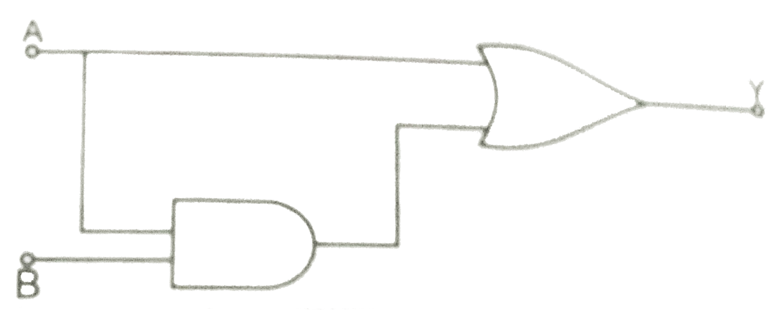
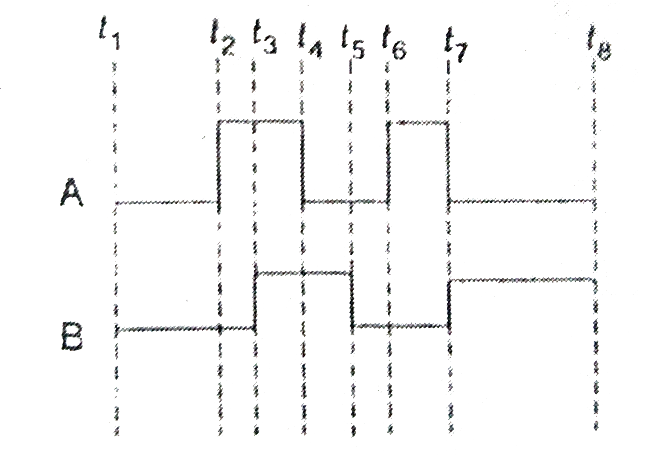
Show output waveform for all possible inputs of A and B.

Topper's Solved these Questions
- SEMI-CONDUCTORS ELECTRONICSBOOK - OSWAAL PUBLICATIONCHAPTER - SEMI-CONDUCTORS ELECTRONICSEXERCISE - TOPIC -4 LOGIC GATES (SHORT ANSWER TYPE QUESTIONS-II)
2 Videos
- SEMI-CONDUCTORS ELECTRONICSBOOK - OSWAAL PUBLICATIONCHAPTER - SEMI-CONDUCTORS ELECTRONICSEXERCISE - TOPIC -4 LOGIC GATES (NUMERICAL PROBLEMS)
4 Videos
- SEMI-CONDUCTORS ELECTRONICSBOOK - OSWAAL PUBLICATIONCHAPTER - SEMI-CONDUCTORS ELECTRONICSEXERCISE - TOPIC -4 LOGIC GATES (VERY SHORT ANSWER TYPE QUESTIONS)
3 Videos
- Sample Paper 8BOOK - OSWAAL PUBLICATIONCHAPTER - Sample Paper 8EXERCISE - Exercise
37 Videos
- SOLVED PAPER (II PUC JULY 2016)BOOK - OSWAAL PUBLICATIONCHAPTER - SOLVED PAPER (II PUC JULY 2016)EXERCISE - PART D
11 Videos
Similar Questions
The output of a 2-inputs NAND gate is fed to a NOT gate. Write down the truth table for the output of the combination for all possible input of the combination for all possible inputs of A and B.
View SolutionIn the following circuit, the output Y for all possible inputs A and B is expressed by the truth table:

View Solution
Knowledge Check
In the following circuit, the output Y for all possible inputs A and B is expressed by the truth table:
 A∣∣ ∣ ∣ ∣ ∣ ∣∣ABY000010100111∣∣ ∣ ∣ ∣ ∣ ∣∣B∣∣ ∣ ∣ ∣ ∣ ∣∣ABY001011101110∣∣ ∣ ∣ ∣ ∣ ∣∣C∣∣ ∣ ∣ ∣ ∣ ∣∣ABY001010100110∣∣ ∣ ∣ ∣ ∣ ∣∣D∣∣ ∣ ∣ ∣ ∣ ∣∣ABY000011101111∣∣ ∣ ∣ ∣ ∣ ∣∣
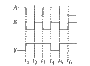
The figure shows the voltage waveforms across two inputs A and B and the output Y of a logic circuit. The logic circuit gate is
 AOR gateBAND gateCNOR gateDNAND gate
Express by a truth table, the output Y for all possible input A and B in the following circuit Fig.

View Solution(a) Draw the circuit diagram of a full wave rectifier using p-n junction diole. Explain its working and show the output, input waveforms.
(b) Show the output waveforms (Y) for the following inputs A and B of (i) OR gate (ii) NAND gate :

View SolutionDraw the output waveform X, using the given inputs A and B for the logic circuit shows below. Also, identify the logic operation performed by this circuit.

View SolutionDraw the output waveform X, using the given inputs A and B for the logic circuit shows below. Also, identify the logic operation performed by this circuit.

View SolutionDraw the output waveformed at X, using the given inputs A and B for the logic circuit shows below. Also, identify the logic operation performed by this circuit.

View SolutionDraw the output waveformed at X, using the given inputs A and B for the logic circuit shows below. Also, identify the logic operation performed by this circuit.

View Solution

