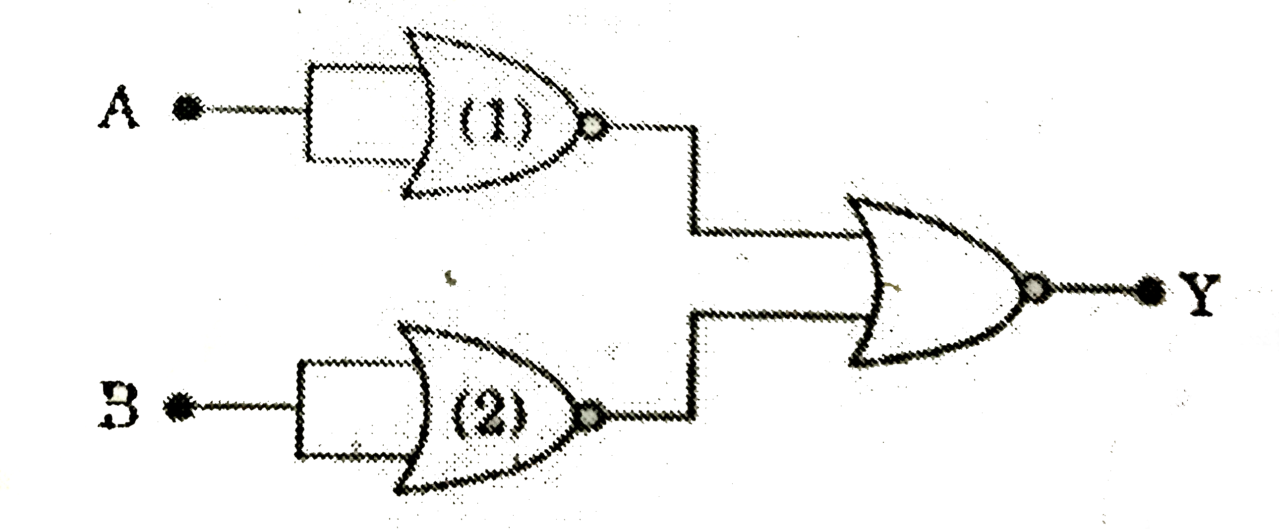
The inputs A and B are inverted by using two NOT gates and their outputs are fed to the NOR gate as shown:
Analyse the action of the gates (1) and (2) and identify the logic gate of the complete circuit so obtained. Give its symbol and the truth table.

Text Solution
The output Y=¯¯¯¯¯¯¯¯¯¯¯¯¯¯¯A+¯¯¯B=¯¯¯¯¯¯¯A.¯¯¯¯¯¯B=A.B
(i) The gates (1) and (2) act as NOT gate (made from NOR gates).
(ii) The logic gate of the complete circuit is AND gate.
Symbol:

|
Topper's Solved these Questions
Similar Questions
Knowledge Check
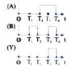
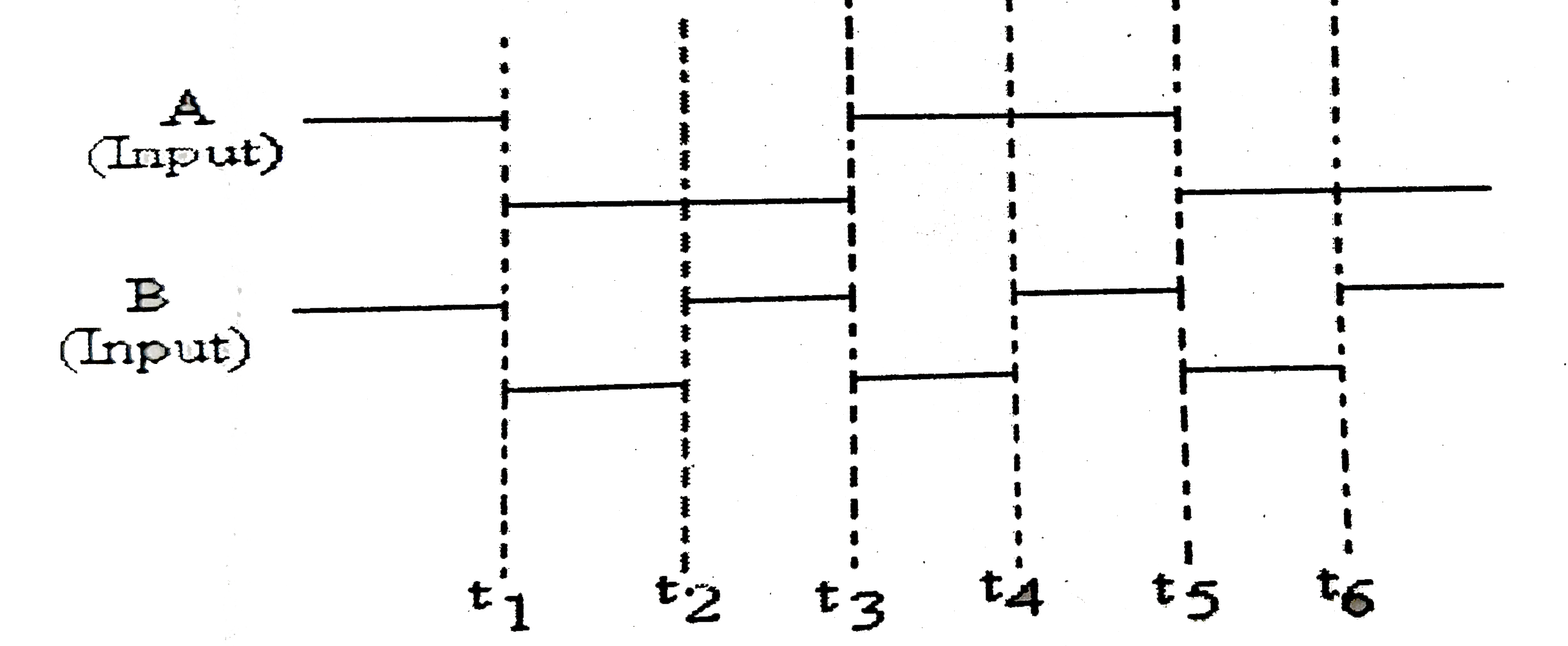
The input and the output wave form of a logic gate is shown in diagraam, then identify the logic gate :
 AAND gateBOR gateCNAND gateDNOT gate
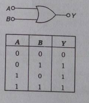
A logic gate and its truth table are shown below

The gate is :ANORBANDCORDNOTA logic gate and its truth table are shown below

The gate is :ANORBANDCORDNOT
Give logic symbol and truth table for a NOT gate.
View SolutionThe output of a 2-input AND gate is fed to a NOT gate. Give the name of the combination and its logic symbol. Write down its truth table.
View SolutionThe output of a 2-input AND gate is fed to a NOT gate. Give the name of the combination and its logic symbol. Write down its truth table.
View SolutionDraw the logic symbol of NAND gate and give its Truth table
View SolutionGive the truth table for NOR gate.
View Solution

