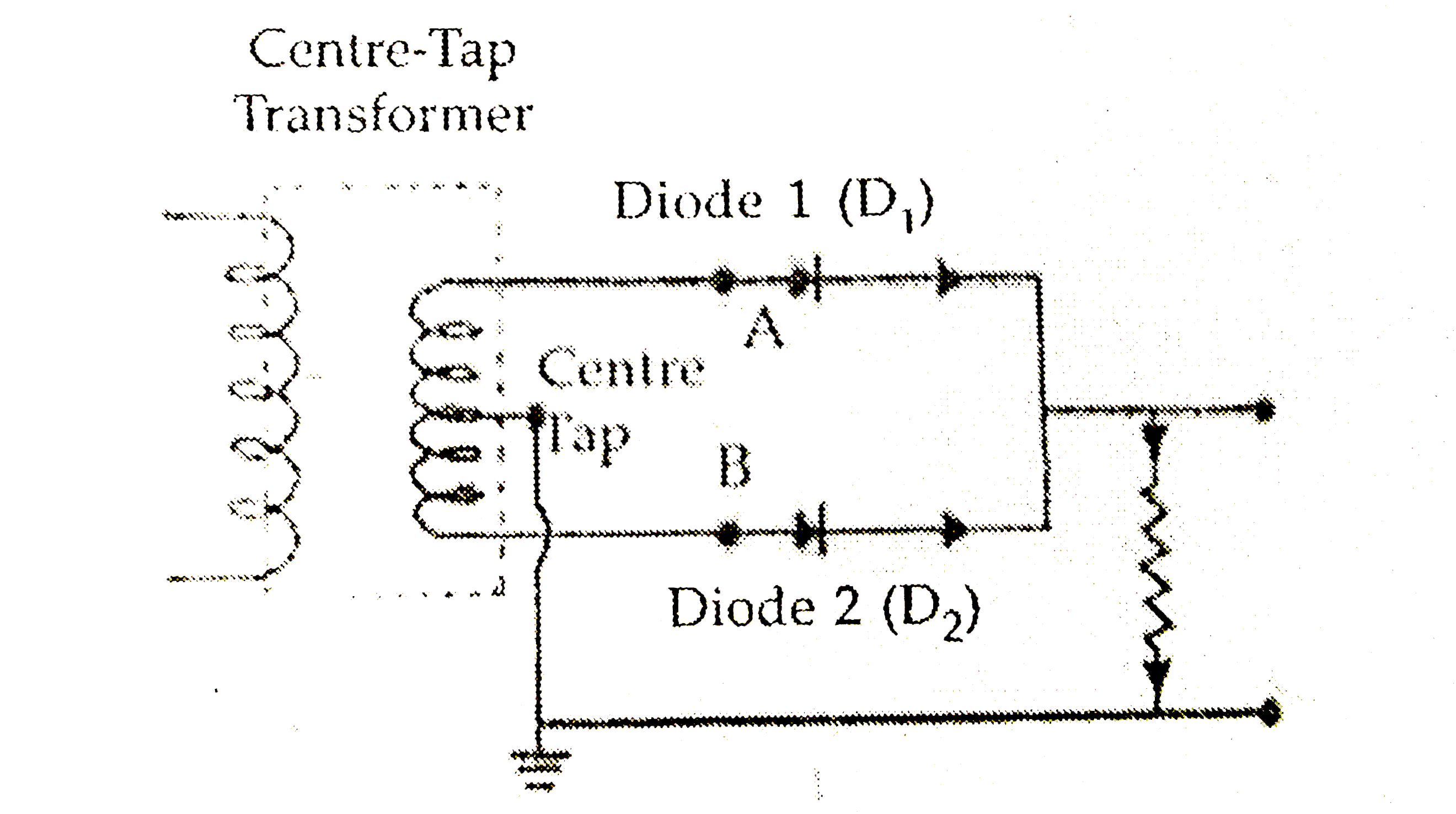
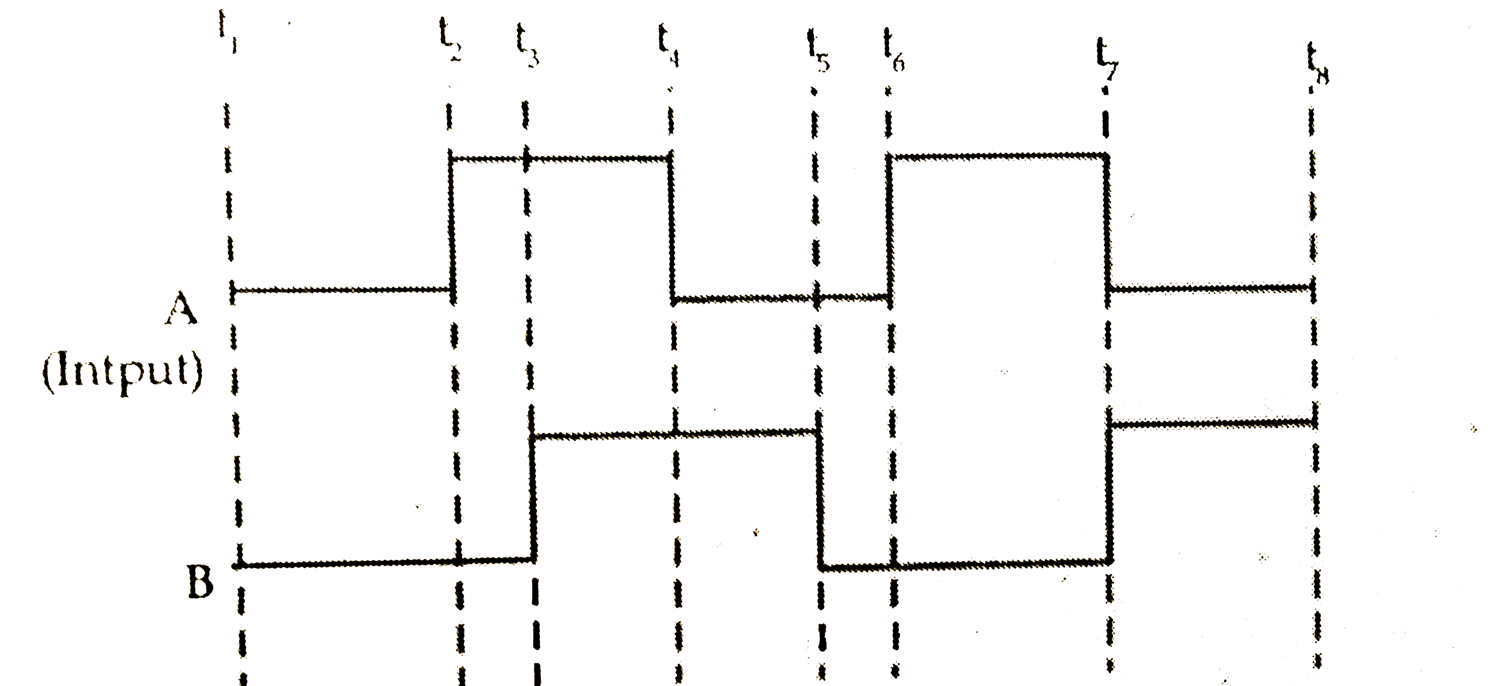
(a) In the figure given below the input waveform is converted into the output waveform by a device 'X'. Name the device and draw its circuit diagram.

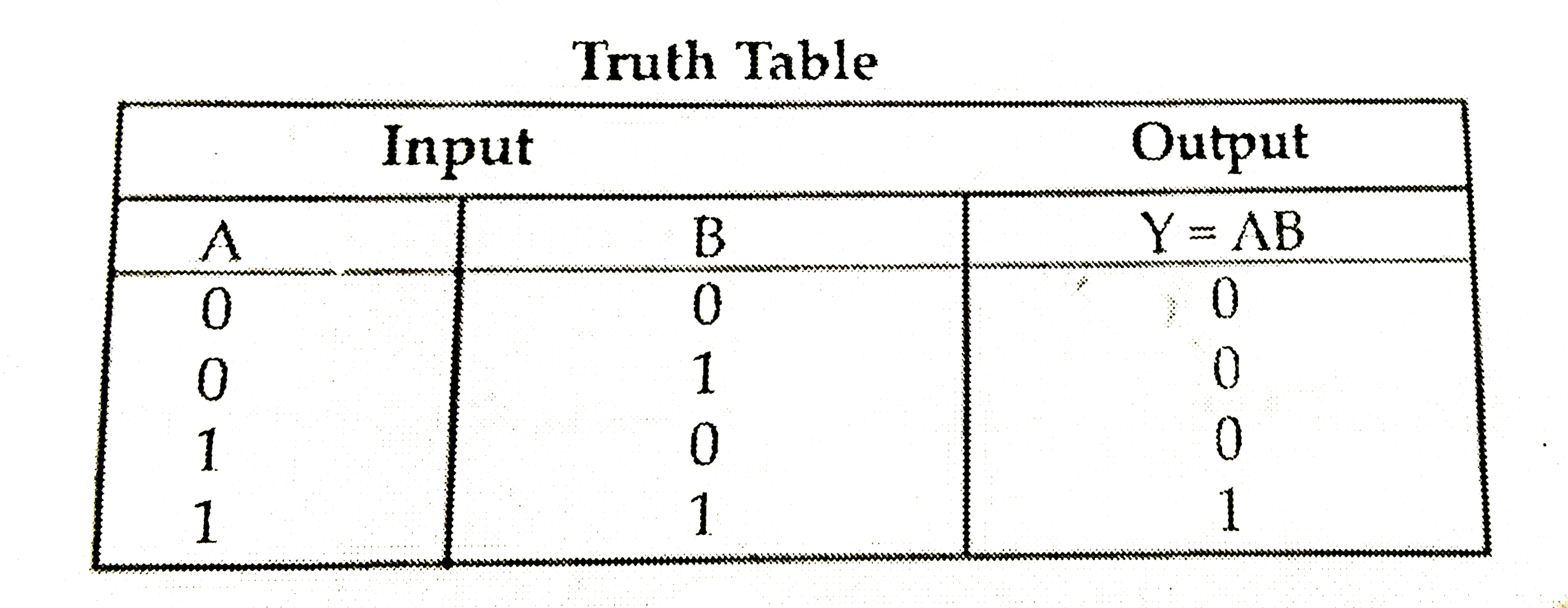
(b) Identify the logic gate represented by the circuit as shown and write its truth table.

(a) The device name (x) is full wave rectifier. Circut diagram is given below :

(b) Logic gate represented by the circuit is AND gate.


Topper's Solved these Questions
- XII BOARDSBOOK - XII BOARDS PREVIOUS YEARCHAPTER - XII BOARDSEXERCISE - SET-II
35 Videos
- XII BOARDSBOOK - XII BOARDS PREVIOUS YEARCHAPTER - XII BOARDSEXERCISE - SET-III
25 Videos
- XII BOARDSBOOK - XII BOARDS PREVIOUS YEARCHAPTER - XII BOARDSEXERCISE - SET III
9 Videos
- SAMPLE PAPER 2019BOOK - XII BOARDS PREVIOUS YEARCHAPTER - SAMPLE PAPER 2019EXERCISE - SECTION D
6 Videos
Similar Questions
Knowledge Check
In the figure, the input waveform is converted into the output waveform by a device X. The devise X is a/an
 AamplifierBhalf wave rectifierCfull wave rectifierDoscillator
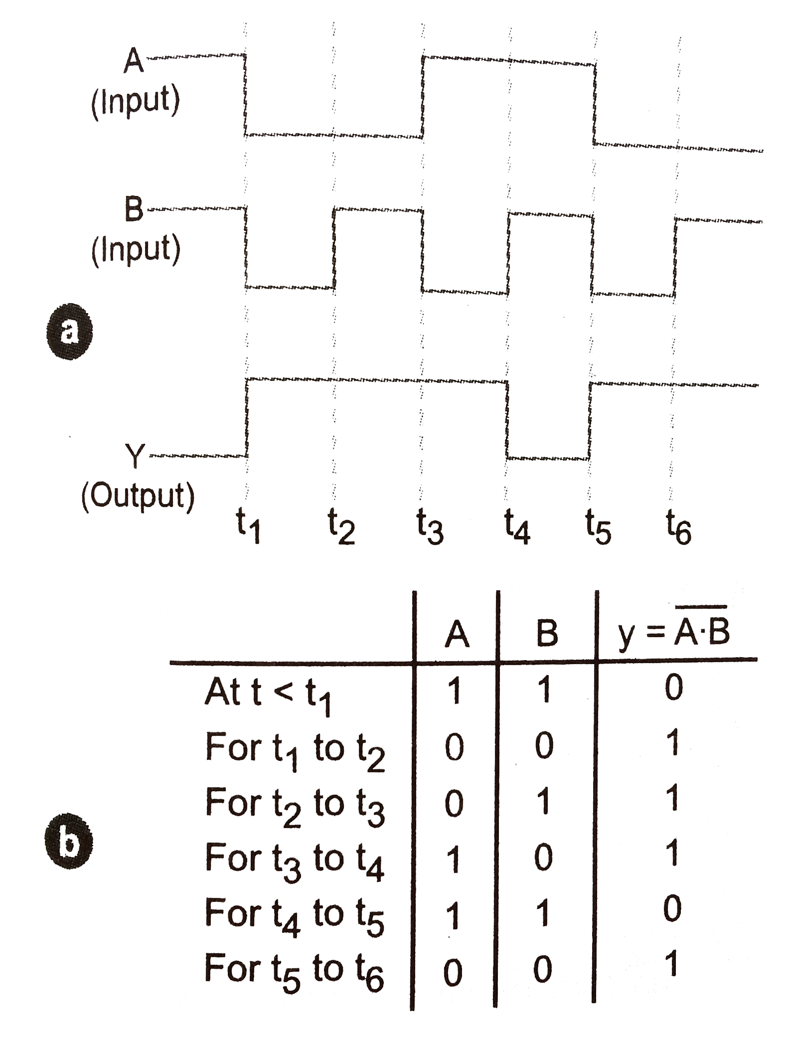
Drawn the output waveform at X, using thye given inputs A and B for the logic circuit shown in Fig. Also identify the logic operation performed by this circuit.

View SolutionUsing the wave forms of the input A and B, draw the output waveform of the given logic circuit . Identify the logic gate obtained . Write also the truth table.

View SolutionUsing the wave forms of the input A and B, draw the output waveform of the given logic circuit . Identify the logic gate obtained . Write also the truth table.

View SolutionThe figure shows the input weveforms A and B for 'AND' gate Draw the output waveform and write the truth table for this logic gate
 .
.
View SolutionDraw the output waveform X, using the given inputs A and B for the logic circuit shows below. Also, identify the logic operation performed by this circuit.

View SolutionDraw the output waveform X, using the given inputs A and B for the logic circuit shows below. Also, identify the logic operation performed by this circuit.

View SolutionDraw the output waveformed at X, using the given inputs A and B for the logic circuit shows below. Also, identify the logic operation performed by this circuit.

View Solution

