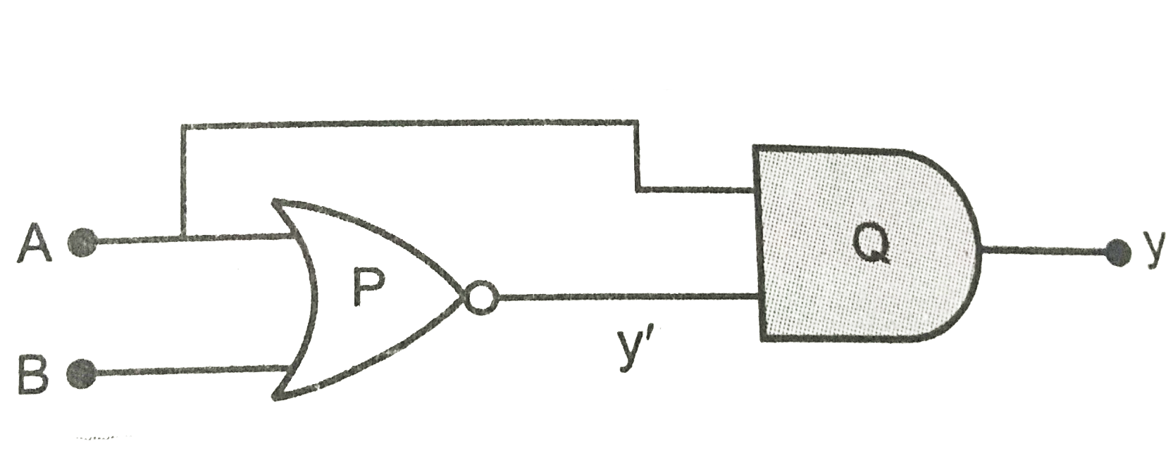
Identify the gates P and Q shown in the figure. Write the truth table for the combination of the gates shown.

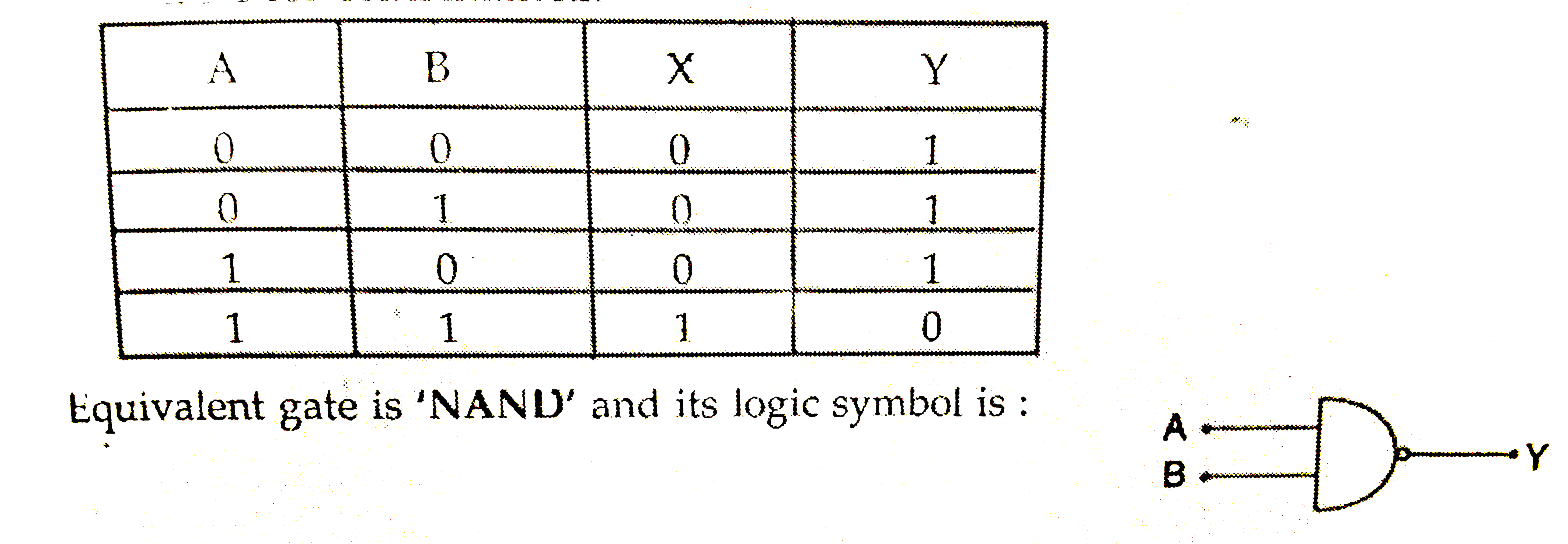
Name the equivalent gate representing this circuit and write its logic symbol.
Video Solution
Text Solution
(i) P acts as AND gate, Q as NOT gate .
Truth table for combinationn of gates P and Q :

|
Updated on:21/07/2023
Topper's Solved these Questions
- BOOK - XII BOARDS PREVIOUS YEARCHAPTER - XII BOARDSEXERCISE - section -D3videos
XII BOARDS
- BOOK - XII BOARDS PREVIOUS YEARCHAPTER - XII BOARDSEXERCISE - section -E15videos
XII BOARDS
- BOOK - XII BOARDS PREVIOUS YEARCHAPTER - XII BOARDSEXERCISE - section B5videos
XII BOARDS
- BOOK - XII BOARDS PREVIOUS YEARCHAPTER - SAMPLE PAPER 2019EXERCISE - SECTION D6videos
SAMPLE PAPER 2019
Similar Questions
Knowledge Check
- Question 1 - Select One
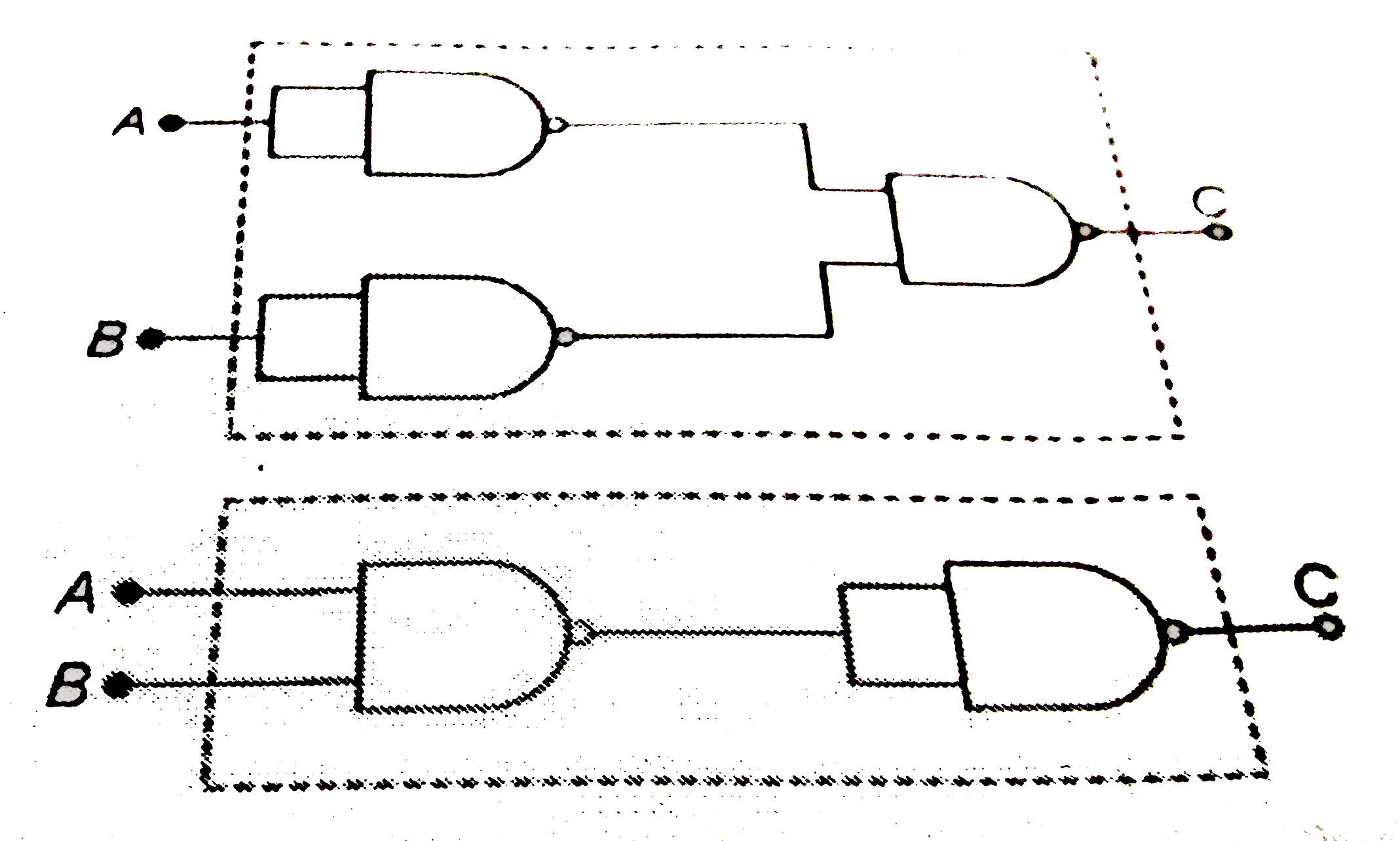
The combination of the gates shown represents :-
_E01_431_Q01.png) AAND gateBOR gateCNAND gateDNOR gate
AAND gateBOR gateCNAND gateDNOR gate - Question 2 - Select One
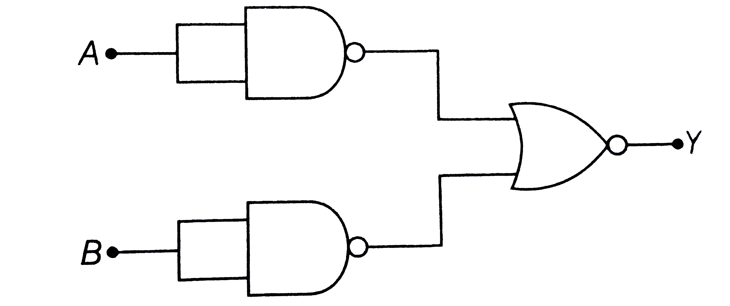
The truth table for the following combination of gates is :-
_E01_430_Q01.png) AABY000010101111BABY000010101111CABY001011101110DABY000011101110
AABY000010101111BABY000010101111CABY001011101110DABY000011101110 - Question 3 - Select One
The combination of gates shown here are equivalent to
 AOR gate and an AND gate respectivelyBAND gate and a NOT gate respectivelyCAND gate and an OR gate respectivelyDOR gate and a NOT gate respectively
Identify the logic gates marked P and Q in the circuit Fig. Write the truth table for this combination.
 View Solution
Write the truth table of AND gate.
View SolutionThe combination of the gates shown represents : -
 View Solution
The combination of the gates shown in the figure results in
 View Solution
The combination Of NAND gates shown in the figure
 View Solution


