Suggest an ideal to convert a full wave bridge rectifier to a half wave rectifier by changing the connecting wire/s. Draw the diagram and explain your answer.
Text Solution
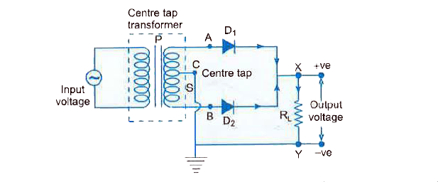
The circuit diagram of a full wave rectifier is given here. In one half cycle we get output due to D1 because it is in forward bias and D2 is in reverse bias. However, in next half cycle we get output due to D2 because now it is in forward bias and D1 is in reverse bias.

If in the circuit shown Y point is directly connected to point B, the arrangement will behave as a half wave rectifier. It is because in one half cycle when D1 is in forward bias, we shall get output across RL. However in second half cycle we do not get any output because now circuit is not completed. So the arrangement acts as a half wave rectifier only.
|
Topper's Solved these Questions
- CBSE SAMPLE QUESTION PAPER 2019-20 (SOLVED)BOOK - U-LIKE SERIESCHAPTER - CBSE SAMPLE QUESTION PAPER 2019-20 (SOLVED)EXERCISE - SECTION D
6 Videos
- CBSE SAMPLE QUESTION PAPER 2019-20 (SOLVED)BOOK - U-LIKE SERIESCHAPTER - CBSE SAMPLE QUESTION PAPER 2019-20 (SOLVED)EXERCISE - SECTION B
9 Videos
- CBSE EXAMINATION PAPER 2020 (SOLVED) BOOK - U-LIKE SERIESCHAPTER - CBSE EXAMINATION PAPER 2020 (SOLVED) EXERCISE - SECTION - D
6 Videos
- CURRENT ELECTRICITY BOOK - U-LIKE SERIESCHAPTER - CURRENT ELECTRICITY EXERCISE - SELF ASSESSMENT TEST (SECTION C )
3 Videos
Similar Questions
Suggest an idea to convert a full wave bridge rectifier to a half wave rectifier by changing the connecting wire/s. Draw the diagram and explain your answer.
View SolutionSuggest an idea to convert a full wave bridge rectifier to a half wave rectifier by changing the connecting wire/s. Draw the diagram and explain your answer.
View Solution
Knowledge Check
Which is the correct diagram of a half-wave rectifier
A B
B C
C D
D
Which is the correct diagram of a half- wave reactifier?
A B
B C
C D
D
In comparison to a half wave rectifier, the full wave rectifier gives lower
AEfficiencyBAverage dcCAverage output voltageDNone of these
Give any two difference between a half wave rectifier and a full wave rectifier.
View SolutionGive any two differences between a half-wave rectifier and a full-wave rectifier.
View SolutionDraw the circuit diagram of a half wave rectifier. Hence explain its working.
View SolutionWhat is the value of a ripple factor for a half wave and a full wave rectifier
View SolutionWhich of the following is the correct diagram of a half-wave rectifier?
View Solution
