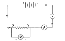
An electric circuit consisting of a 0.5 m long nichrome wire XY, an ammeter, a voltmetu, four cells. of 1.5V each and a plug key wu Id up. Draw a diagram of this drcuit in the 'ON' po1ltlon. Following graph Wi8 plotted between the value of potential difference (V) and electric current (I). State the concluion that you draw about the relation between V and I from thll graph.
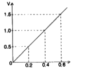
Placement of ammeter, voltmeter, direction of current 4 cells in series with a closed key.
Relation : For a given resistance, current flowing through a conductor is directly proportional to potential difference across it, if other physical conditions remain constant i.e., V∝I .
Topper's Solved these Questions
- BOOK - OSWAAL PUBLICATIONCHAPTER - ELECTRICITYEXERCISE - TOPIC-1 (Long Answer Type Questions )15videos
ELECTRICITY
- BOOK - OSWAAL PUBLICATIONCHAPTER - ELECTRICITYEXERCISE - TOPIC-2 ( Multiple Choice Questions )2videos
ELECTRICITY
- BOOK - OSWAAL PUBLICATIONCHAPTER - ELECTRICITYEXERCISE - TOPIC-1 (Short Answer Type Questions -I)13videos
ELECTRICITY
- BOOK - OSWAAL PUBLICATIONCHAPTER - LIGHT-REFLECTION AND REFRACTIONEXERCISE - NCERT CORNER (TEXTBOOK EXERCISES)15videos
LIGHT-REFLECTION AND REFRACTION
Similar Questions
(a) Name an instrument that measures electric current in a curcuit. Define the unit of eletric current.
(b) What do the following symbols, (Fig. 3.58) mean in a circuit diagram ?
( c) An electric circuit consisting of a 0.5m long nichrome wire XY, an ammeter, a voltmeter, four cells of 1.5V each and a plug key was set up.
(i) Draw a diagram of this electric circuit to study the relation between the potential difference maintained between the points 'X' and 'Y' and the electric current flowing through XY.
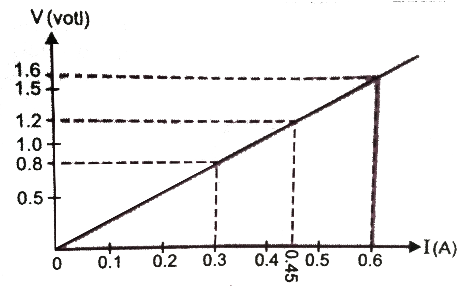
(ii) Graph shown in (Fig. 3.59) was plotted VandI values.
What would be the values of v/I ratios when the potential differences are 0.8V,1.2Vand1.6V respectively ? What conclusion do you draw from these values ?
 ,
,
 .View Solution
(a) Name an instrument that measures electric current in a circuit. Define the unit of electric current.
(b) What do the following symbols represent in a circuit diagram?

(c) An electric circuit consisting of a 0.5 m long nichrome wire XY, an ammeter, a voltmeter, four cells of 1.5 V each and a plug key was set up.
(i) Draw the electric circuit diagram to study the relation between the potential difference maintained between the points 'X' and 'Y' and the electric current flowing through XY.
(ii) Following graph was plotted between Vand I values using above circuit:
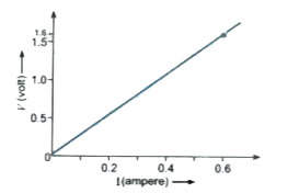
What would be the values of ratios when the potential difference is 0.8 V, 1.2 V and 1.6 respectively? What conclusion do you draw from these values?View Solution
Knowledge Check
- Question 1 - Select One
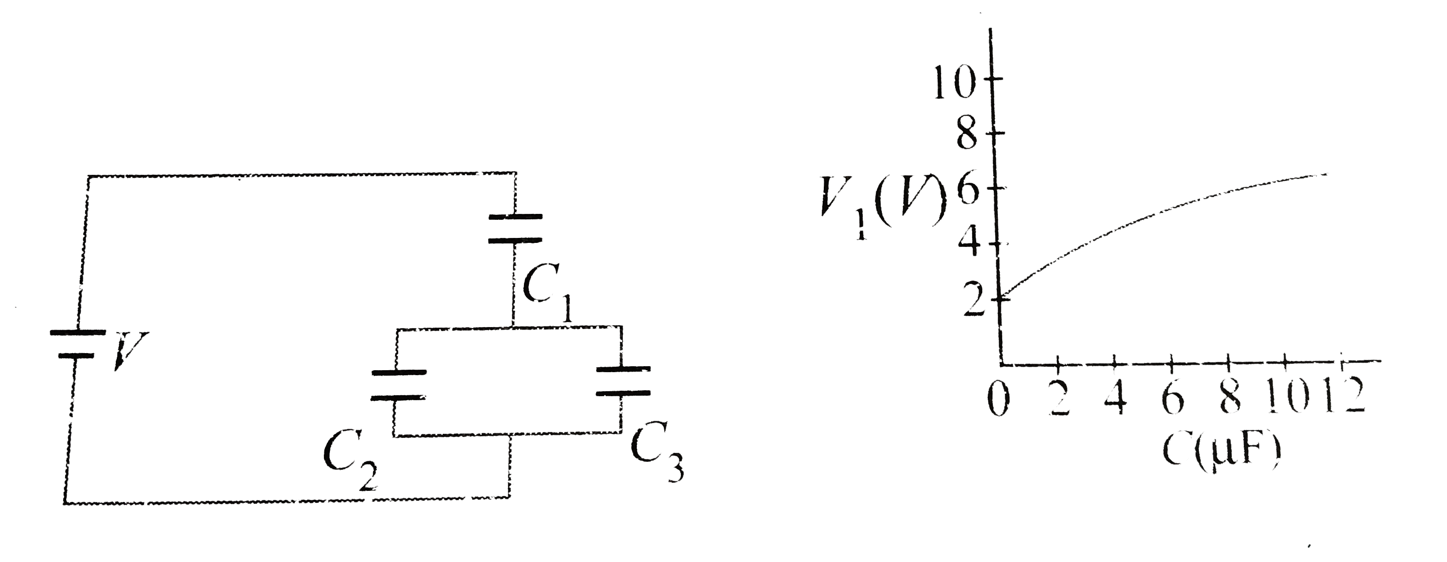
Capacitor C3 in the circuit is a variable capacitor (its capacitance can be varied). C1andC2 are of fixed values. Graph is plotted between potential difference V1 (across capacitor C1) versus C3. Electric potential V1 approches on asymptote of 10 V as C3∝∞.
 ,
,
Relation between C1andC2 isAC1=C2BC1=4C2C4C1=C2Dany relation
(a) The components of an electric circuit are 0.5 m long nichrome wire XY, an ammeter, a voltmeter, four cells of 1.5 V each, rheostat and a plug key. Draw a circuit diagram to study the relation between potential difference across the terminals X and Y of the wire and current flowing through it.
(b) State the law that relates potential difference across a conductor with the current flowing through it.View SolutionIn an experiment of verification of Ohm's law, following observations are obtained.

Draw a V-I graph and use this graph to find :
the potential difference V when the current / is 0-5 A,View SolutionYou have following material :
An ammeter ( 0-1A0 ,a voltmeter ( 0-3V) , a resistor of 20Ω , a key, a rheostat, a battery of 3 V and seven connecting wires.
Using this material draw a labelled circuit diagram to study the dependence of potential difference (V) across a resistor ont he current (I) passing through it.View SolutionYou have following material :
An ammeter ( 0-1A0 ,a voltmeter ( 0-3V) , a resistor of 20Ω , a key, a rheostat, a battery of 3 V and seven connecting wires.
Using this material draw a labelled circuit diagram to study the dependence of potential difference (V) across a resistor ont he current (I) passing through it.View Solution(i) Draw a schematic diagram of a circuit consisting of a battery of five 2V cells, a 5Ω resistor, a10Ω resistor and a 15Ω resistor and a plug key all connected in series.
(ii) Calculate the electric current passing through the above circuit when the key is closed.
(iii) Potential difference across 15Ω resistor.View SolutionDraw a schematic diagram of a circuit consisting of a battery of 3 cells of 2V each, a combination of three resistors of 10Ω,20Ω and 30Ω connected in a parallel, a plug key and an ammeter, all connected in series. Use the circuit to find the value of the following :
(a) current through each resistor
(b) total current in the circuit.
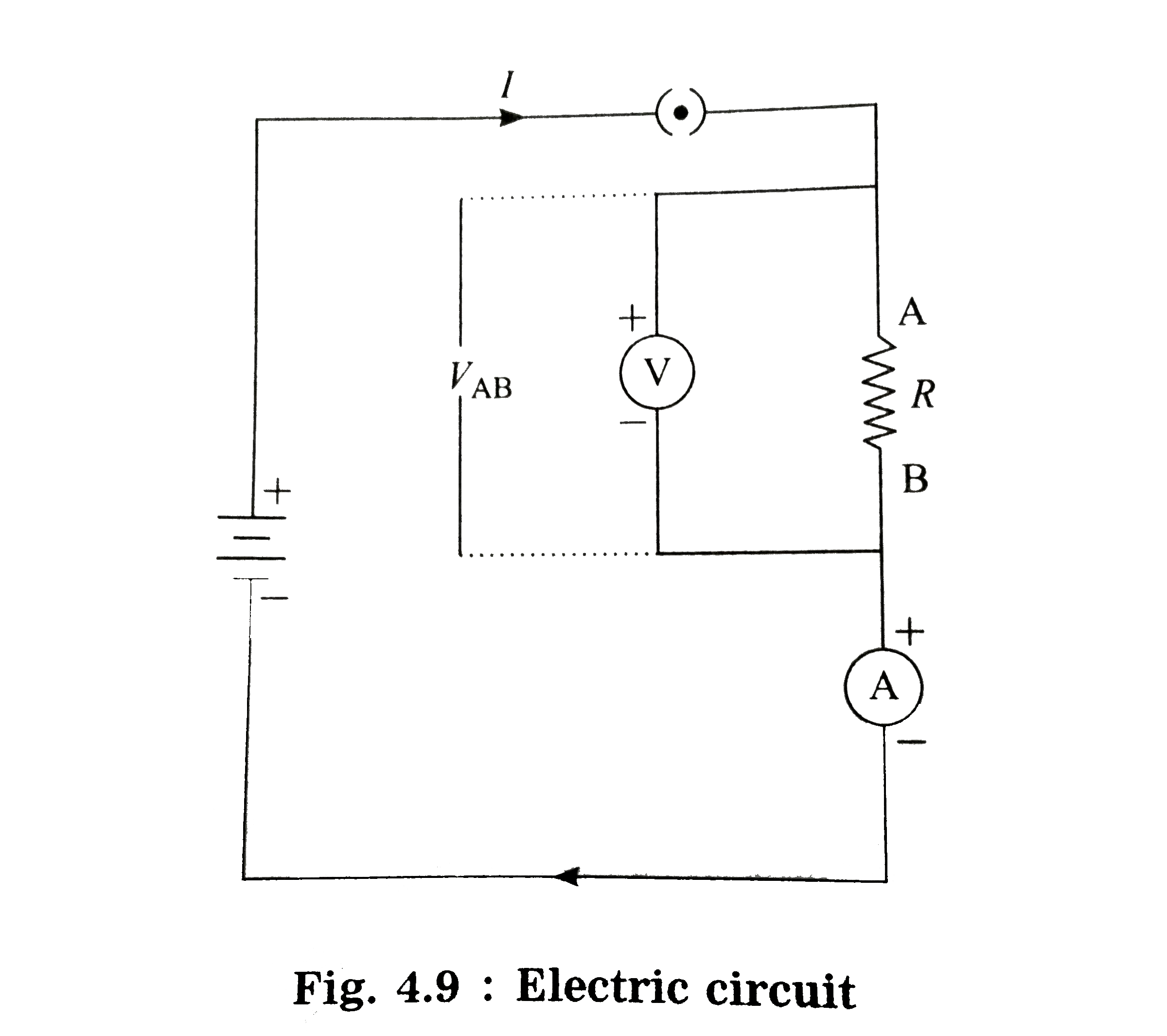
(c ) total effective resistance of the circuit.View SolutionMaterial : Connecting wires , electric cells, electrical resistance, voltmeter , ammeter , plug key.
Procedure : Connect the circuit as shown in the accompanying figure after taking the components with proper values. Measure the current (I). Also measure the potential difference (V)AB between the two ends (A and B) of the resistance .
The potential at A is higher than the potential at B as the point A is connected to the positive electrode of the cell and the point B to the negative electrode of the cell.
What happens to this energy?View Solution
