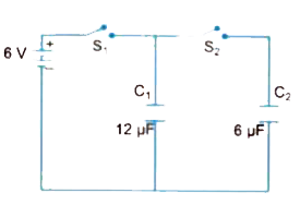
We have two capacitors C1andC2 of capacitance 12μF and 6μF respectively. As shown in the given circuit arrangement the two capacitors are joined to a power supply of 6 volts. Initially the switch S1 is closed but switch S2 is open. After some time, the switch S1 is opened and simultaneously switch S2 is closed.
Now answer the following questions :
The final value of potential of capacitor C1 is
6 V
4V
2 V
12 V
The correct Answer is:B
Final value of common potential of both capacitors =QC1+C1=C1VC1+C2=12μF×6V(12+6)μF=V
Topper's Solved these Questions
- ELECTROSTATIC POTENTIAL AND CAPACITANCE BOOK - U-LIKE SERIESCHAPTER - ELECTROSTATIC POTENTIAL AND CAPACITANCE EXERCISE - MULTIPLE CHOICE QUESTIONS
35 Videos
- ELECTROSTATIC POTENTIAL AND CAPACITANCE BOOK - U-LIKE SERIESCHAPTER - ELECTROSTATIC POTENTIAL AND CAPACITANCE EXERCISE - FILL IN THE BLANKS
18 Videos
- ELECTROSTATIC POTENTIAL AND CAPACITANCE BOOK - U-LIKE SERIESCHAPTER - ELECTROSTATIC POTENTIAL AND CAPACITANCE EXERCISE - ADDITIONAL EXERCISES
36 Videos
- ELECTROMAGNETICE INDUCTIONBOOK - U-LIKE SERIESCHAPTER - ELECTROMAGNETICE INDUCTIONEXERCISE - Self Assessment Test Section -D
1 Videos
- EXAMINATION PAPER 2020 (SOLVED)BOOK - U-LIKE SERIESCHAPTER - EXAMINATION PAPER 2020 (SOLVED)EXERCISE - SECTION D
6 Videos
Similar Questions
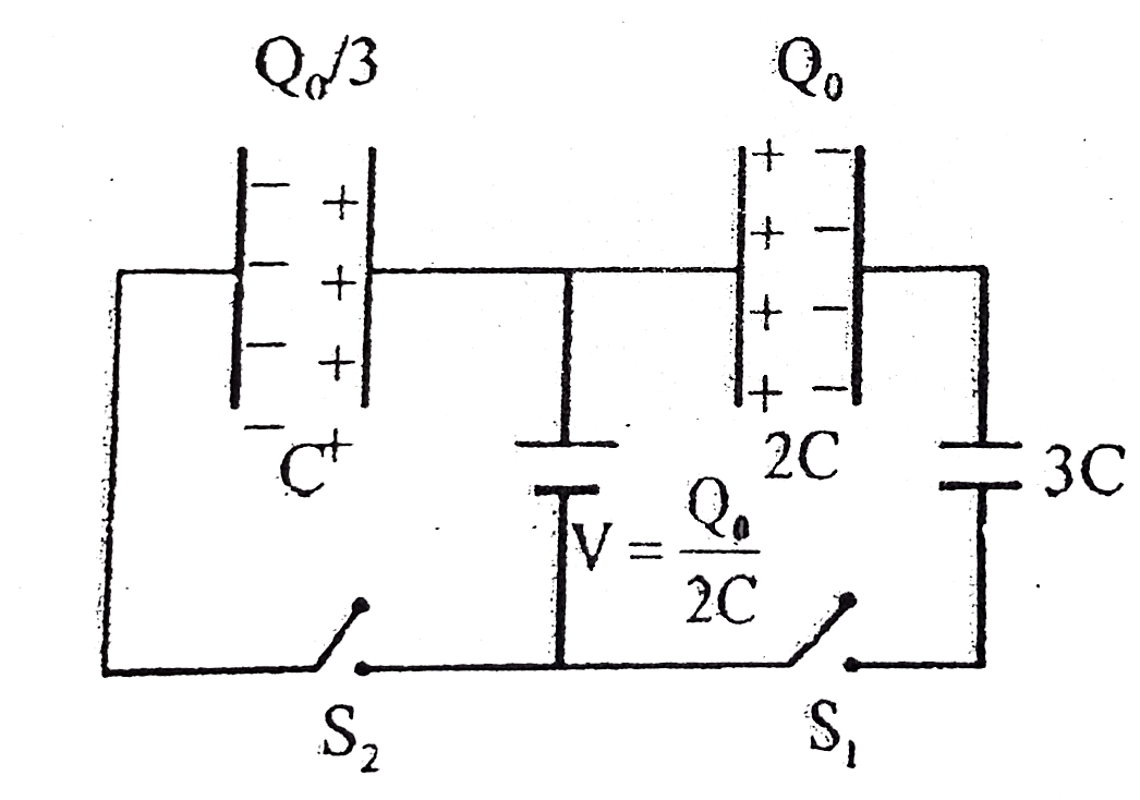
In the given circuit, the initial charges on the capacitors are shown in the figure. The charge flown through the switches S1andS2 respectively after closing the switches are
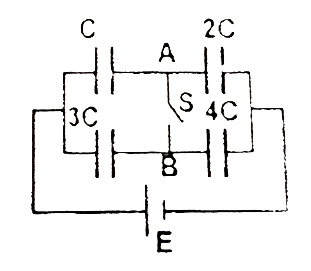
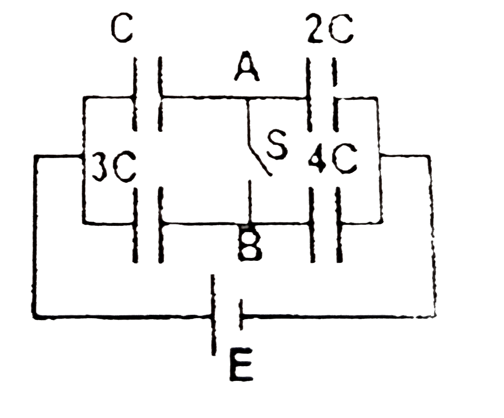
View SolutionFour capacitors of capacitance C, 2C, 3C & 4C respectively are connected as shown in figure. Battery is deal and all the connected wires have no resistance capcitance or inductance. Initially the switch S is open. If at t=0 switch S is closed
Heat generated is the switch after closing switch is
View Solution
Knowledge Check
We have two capacitors C1andC2 of capacitance 12μF and 6μF respectively. As shown in the given circuit arrangement the two capacitors are joined to a power supply of 6 volts. Initially the switch S1 is closed but switch S2 is open. After some time, the switch S1 is opened and simultaneously switch S2 is closed.
Now answer the following questions :
The final value of charge on capacitor C2 isA24μCB48μCC72μCD12μCWe have two capacitors C1andC2 of capacitance 12μF and 6μF respectively. As shown in the given circuit arrangement the two capacitors are joined to a power supply of 6 volts. Initially the switch S1 is closed but switch S2 is open. After some time, the switch S1 is opened and simultaneously switch S2 is closed.
Now answer the following questions :
The fractional loss in electrostatic energy of the arrangement after closing the switch S2 isA14B12C13D34In the circuit shown, the reading of ammeter when switch S is open and when switch S is closed respectively are
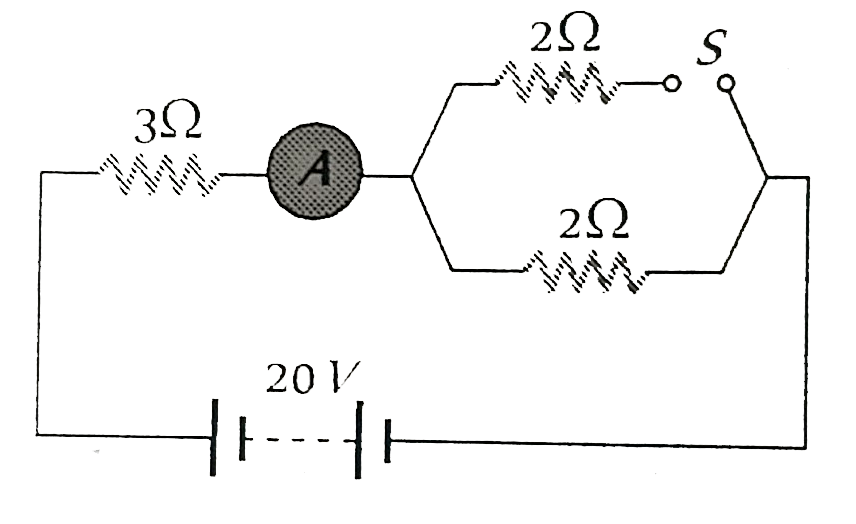 A3A and 4AB4A and 5AC5A and 6AD6A and 7A
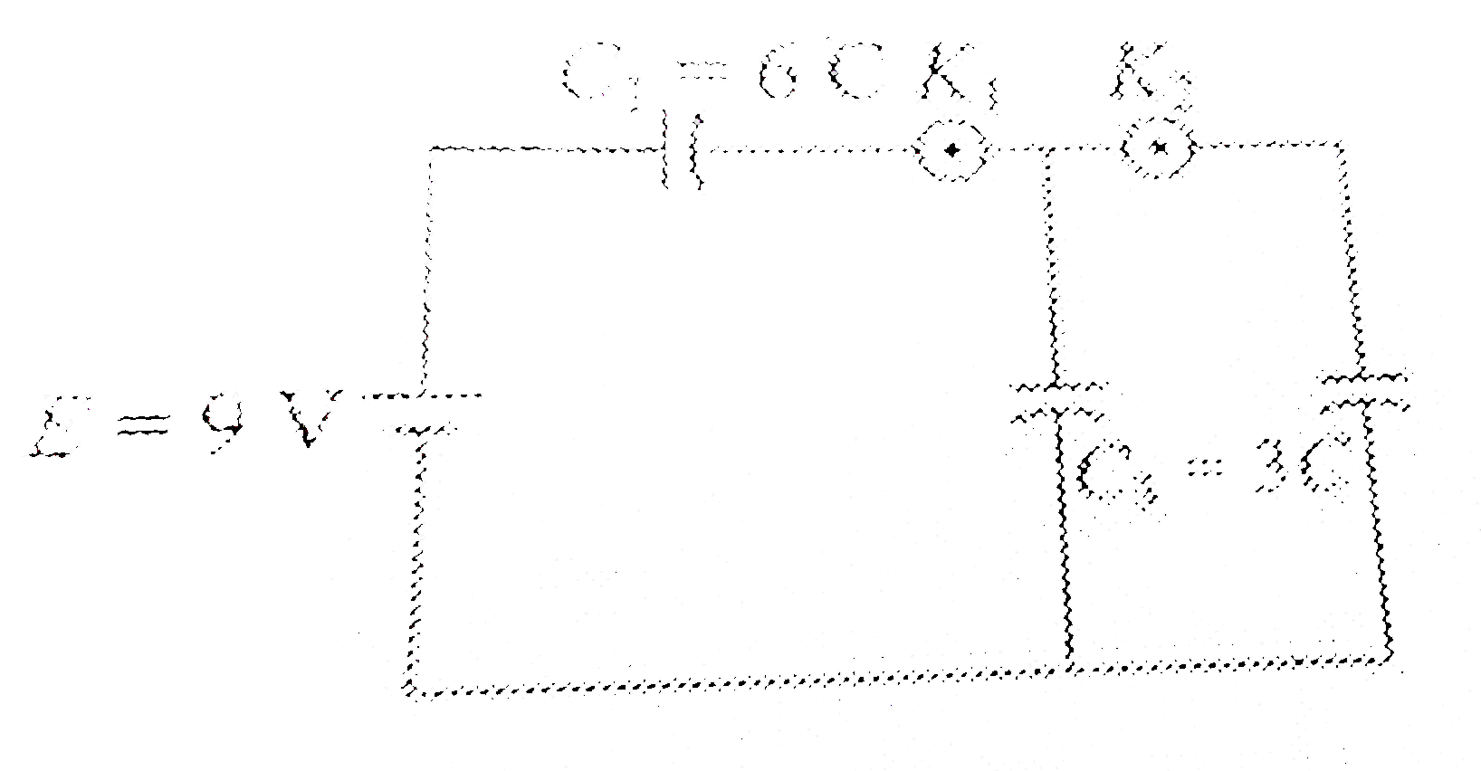
in the circuit shown in the figure initially K1 is closed and K2 is open. What are the charges on each capacitors? Now K1 was opened and K2 was closed (order is important) what will be the charge on each capacitor now? [C=1μF]
View SolutionFour capacitors of capacitance C, 2C, 3C & 4C respectively are connected as shown in figure. Battery is deal and all the connected wires have no resistance capcitance or inductance. Initially the switch S is open. If at t=0 switch S is closed
The work done by battery after closing, switch is
View SolutionIn the given circuit, the initial charges on the capacitors are shown in the figure. The charge flown through the switches S1andS2 respectively after closing the switches are

View SolutionFour capacitors of capacitance C, 2C, 3C & 4C respectively are connected as shown in figure. Battery is deal and all the connected wires have no resistance capcitance or inductance. Initially the switch S is open. If at t=0 switch S is closed
Heat generated is the switch after closing switch is

View SolutionFour capacitors of capacitance C, 2C, 3C & 4C respectively are connected as shown in figure. Battery is deal and all the connected wires have no resistance capcitance or inductance. Initially the switch S is open. If at t=0 switch S is closed
The work done by battery after closing, switch is

View Solution
