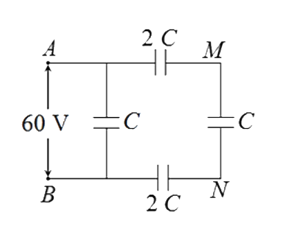
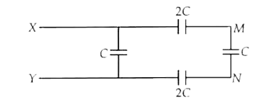
In the circuit shown in figure, a potential difference of 60 V is applied across AB. The potential difference between the points M and N is.

A
10 V
B
15 V
C
20V
D
30 V
Text Solution
The correct Answer is:B
Let Q amount of charge flows through the MN branch.
V=60V=Q2C+QC+Q2C=2QC or Q=30C
Potential difference between M and N=QC=30CCV=30V
|
Updated on:21/07/2023
Topper's Solved these Questions
- BOOK - MTG GUIDECHAPTER - ELECTROSTATICSEXERCISE - NEET ITALS1videos
ELECTROSTATICS
- BOOK - MTG GUIDECHAPTER - ELECTROSTATICSEXERCISE - NEET VITALS18videos
ELECTROSTATICS
- BOOK - MTG GUIDECHAPTER - ELECTROSTATICSEXERCISE - AIPMT/NEET (MCQ.s)34videos
ELECTROSTATICS
- BOOK - MTG GUIDECHAPTER - ELECTRONIC DEVICESEXERCISE - AIPMT/NEET (MCQs)42videos
ELECTRONIC DEVICES
- BOOK - MTG GUIDECHAPTER - MAGNETIC EFFECTS OF CURRENT AND MAGNETISMEXERCISE - AIPMT/NEET (MCQs)48videos
MAGNETIC EFFECTS OF CURRENT AND MAGNETISM
Similar Questions
Knowledge Check
- Question 1 - Select One
In the circuit shown, a potential difference of 60V is applied across AB. The potential difference between the point M and N is
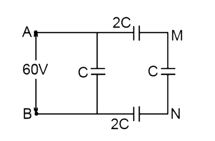 A10 VB15 VC20 VD30 V
 - Question 2 - Select One
In the circuit shown, a potential difference of 60V is applied acrodd.AB. The potential difference between the point M and N is-
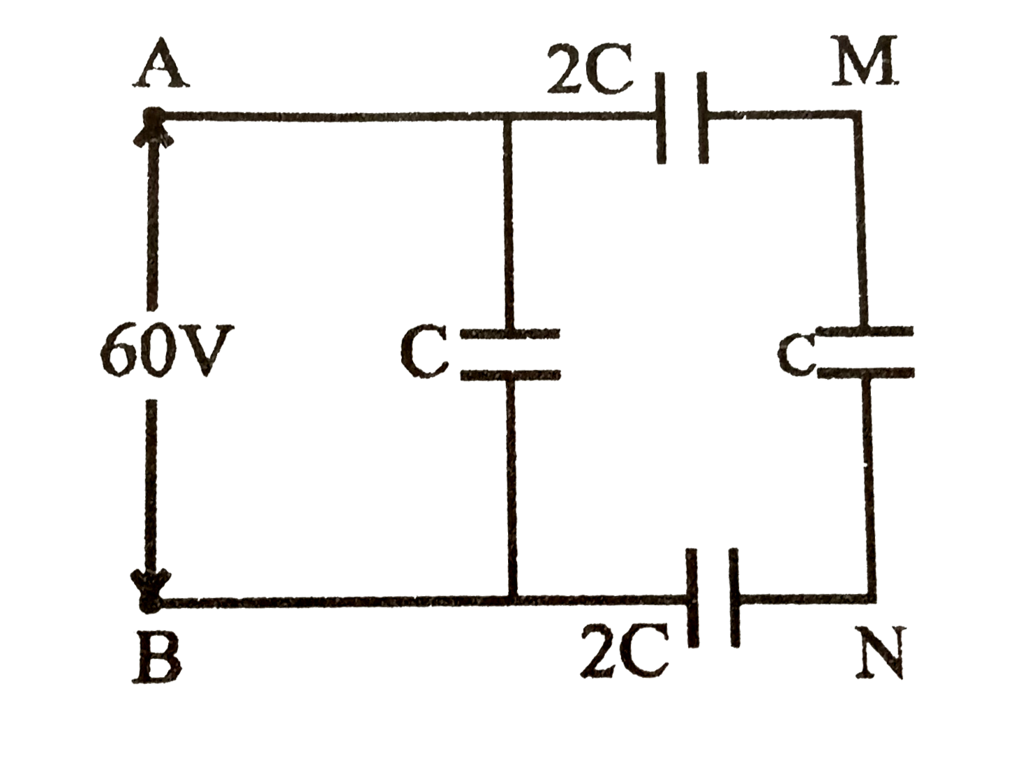 A10VB15C20VD30V
 - Question 3 - Select One
In the circuit shown in figure potential difference between A and B is
 A30 VB60 VC10 VD90 V
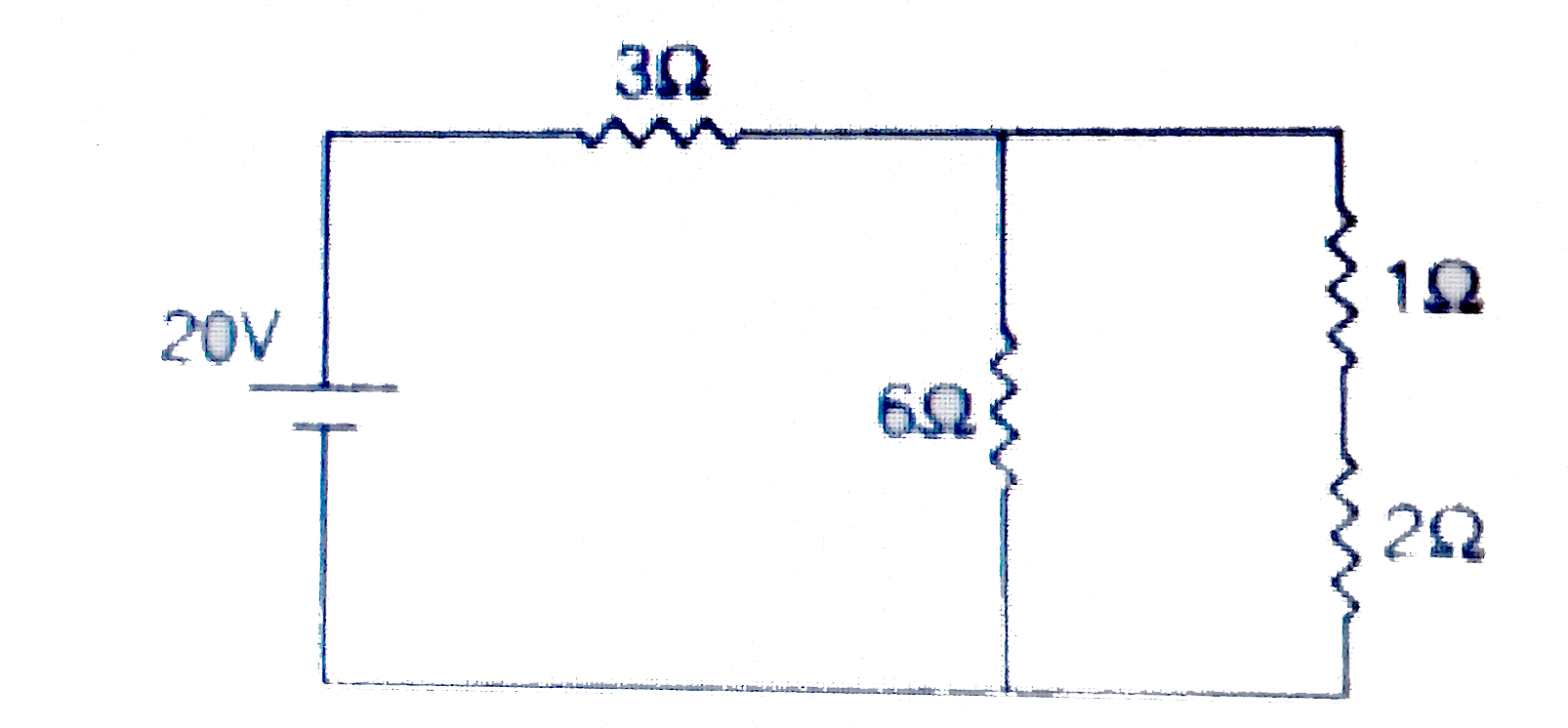
In the circuit shown in figure potential difference across
 View Solution
In the circuit shown in figure potential difference across
 View Solution
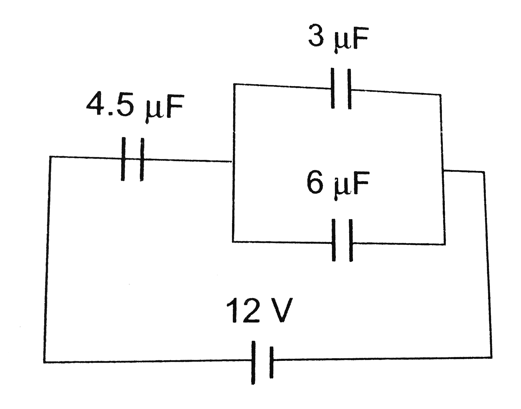
In the circuit shown in the figure, the potential difference across the 4.5μF capacitor is
 View Solution
In the adjoining figure the potential difference between X and Y is 60 V . The potential difference between the points M and N - will be
 View Solution
In the circuit shown in the figure, the potential difference across the 4.5μF capacitor is
 View Solution


