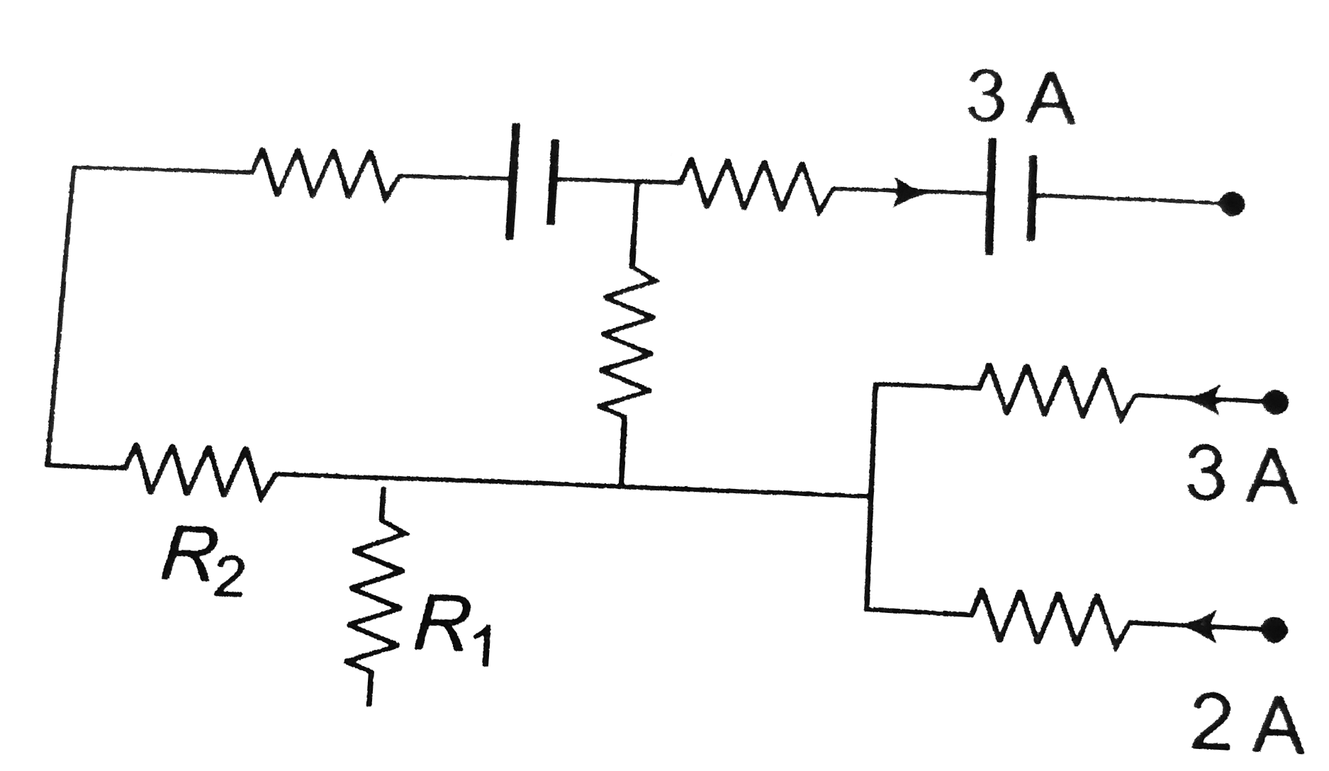
In the circuit shown in the given figure, the resistance R1R2 are respectively

14Ωand40Ω
40Ωand14Ω
40Ωand30Ω
14Ωand30Ω
The correct Answer is:A
Potential difference across 20Ω=20×1
=20V = potential difference across R2. Current in R2=0.5A
∴R2=20V0.5A=40Ω
Potential difference across R1=69V−20V=49V
Current in R1=0.5A+2010A+1A=3.5A
∴R1=493.5=14Ω
Topper's Solved these Questions
- CURRENT ELECTRICITY Book:MTG GUIDEChapter:CURRENT ELECTRICITY Exercise:CHECK YOUR NEET VITALS
Explore 16 Videos
- CURRENT ELECTRICITY Book:MTG GUIDEChapter:CURRENT ELECTRICITY Exercise:MCQs AIPMT / NEET
Explore 32 Videos
- CURRENT ELECTRICITY Book:MTG GUIDEChapter:CURRENT ELECTRICITY Exercise:MCQs AIPMT / NEET
Explore 32 Videos
- ATOMS AND NUCLEIBook:MTG GUIDEChapter:ATOMS AND NUCLEIExercise:AIPMT/NEET(MCQs)
Explore 40 Videos
- DUAL NATURE OF MATTER AND RADIATION Book:MTG GUIDEChapter:DUAL NATURE OF MATTER AND RADIATION Exercise:AIPMT/ NEET MCQs
Explore 30 Videos
Similar Questions
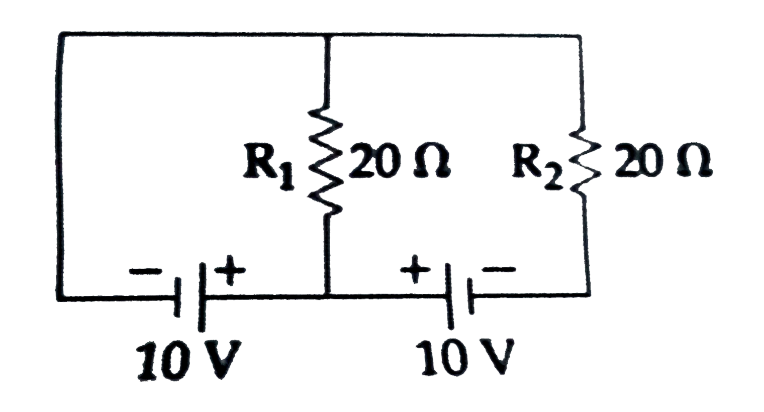
In the given circuit the cells have zero internal resistance. The currents (in Amperes) passing through resistance R1andR2 respectively, are :

View SolutionIn the given circuit the cells have zero internal resistance. The currents (in Amperes) passing through resistance R1andR2 respectively, are :

View Solution
Knowledge Check
In the circuit shown in the given figure, the resistances R1andR2 are respectively
 A14Ωand40ΩB40Ωand44ΩC40Ωand30ΩD14Ωand30Ω
In the shown in the given figure, the resistances R1andR2 are respectively
 A14Ωand40ΩB40Ωand44ΩC40Ωand30ΩD14Ωand30Ω
In the given circuit if I1 and I2 be the current in resistance R1 and R2 respectively then:
 AI1=3A,I2=2ABI1=0,I2=2ACI1=2A,I2=2ADI1=2A and I2 can’t be determined with given data
Three resistors R1,R2 and R3 are to be combined to form an electrical circuit as shown in the figure. It is found that when R1R2andR3 are put respectively in positions A, B and C, the effective resistance of the circuit is 70 ΩWhen R2,R3andR1 are put respectively in position A, B and C the effective resistance is 35Ω and when R3,R1andR2 are respectively put in the position A, B and C, the effective resistance is 42Ω
If R1,R2 andR3are put in series, the effective resistance will be
View SolutionThree resistors R1,R2 and R3 are to be combined to form an electrical circuit as shown in the figure. It is found that when R1R2andR3 are put respectively in positions A, B and C, the effective resistance of the circuit is 70 ΩWhen R2,R3andR1 are put respectively in position A, B and C the effective resistance is 35Ω and when R3,R1andR2 are respectively put in the position A, B and C, the effective resistance is 42Ω
If R1,R2andR3 are all connected in parallel, the effective resistance will be
View SolutionThree resistors R1,R2 and R3 are to be combined to form an electrical circuit as shown in the figure. It is found that when R1R2andR3 are put respectively in positions A, B and C, the effective resistance of the circuit is 70 ΩWhen R2,R3andR1 are put respectively in position A, B and C the effective resistance is 35Ω and when R3,R1andR2 are respectively put in the position A, B and C, the effective resistance is 42Ω
The resistanceR1:R2:R3are in the ratio
View SolutionThree resistors R1,R2 and R3 are to be combined to form an electrical circuit as shown in the figure. It is found that when R1R2andR3 are put respectively in positions A, B and C, the effective resistance of the circuit is 70 ΩWhen R2,R3andR1 are put respectively in position A, B and C the effective resistance is 35Ω and when R3,R1andR2 are respectively put in the position A, B and C, the effective resistance is 42Ω
If R1,R2andR3 are all connected in parallel, the effective resistance will be
View Solution
