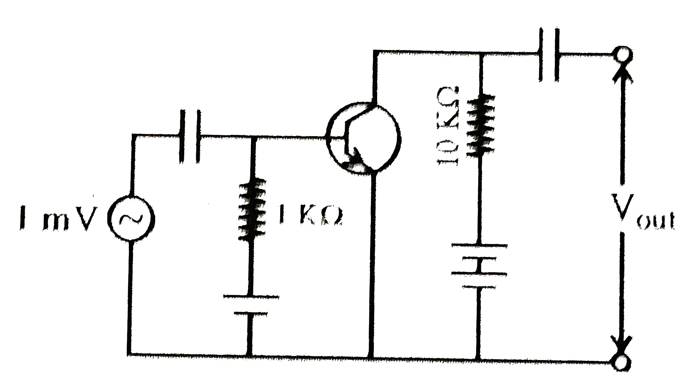
In a common emitter amplifier circuit using a n-p-n transistor, the phase difference between the input and the output voltages will be …….. Solution in Gujrati
135∘
180∘
45∘
90∘
The correct Answer is:B
Step by step video, text & image solution for In a common emitter amplifier circuit using a n-p-n transistor, the phase difference between the input and the output voltages will be …….. by Physics experts to help you in doubts & scoring excellent marks in Class 12 exams.
Topper's Solved these Questions
- BOOK - KUMAR PRAKASHANCHAPTER - SEMICONDUCTOR ELECTRONICS : MATERIALS, DEVICES AND SIMPLE CIRCUITS EXERCISE - Section-D : Multiple Choice Questions (MCQs) (MCQs From .DARPAN. Based On Textbook)116videos
SEMICONDUCTOR ELECTRONICS : MATERIALS, DEVICES AND SIMPLE CIRCUITS
- BOOK - KUMAR PRAKASHANCHAPTER - SAMPLE QUESTION PAPER EXERCISE - PART-B SECTION-C5videos
SAMPLE QUESTION PAPER
- BOOK - KUMAR PRAKASHANCHAPTER - WAVE OPTICSEXERCISE - SECTION-D (MULTIPLCE CHOICE QUESTIONS (MCQS)) (MCQS FROM DARPAN BASED ON TEXTBOOK)239videos
WAVE OPTICS
Similar Questions
Which of the following is not a conductor of electricity?
04:12View SolutionTwo charges –q and +q are located at points (0, 0, –a) and (0, 0, a), respectively.
(a) What is the electrostatic potential at the points (0, 0, z) and (x, y, 0) ?
(b) Obtain the dependence of potential on the distance r of a point from the origin when r/a>>1 .
(c) How much work is done in moving a small test charge from the point (5,0,0) to (–7,0,0) along the x-axis? Does the answer change if the path of the test charge between the same points is not along the x-axis?03:55View SolutionAccording to particle theory of light what is the velocity of light in a dense medium, compared to that in rare medium ?
09:51View SolutionIn common emitter transistor amplifier circuit, the input signal voltage and the output collector voltage are ..............phase.
11:24View SolutionDraw a labelled circuit diagram for a common emitter amplifier using n-p-n transistor. Write down the expression for its voltage gain. What is the phase difference between input and output signals?
01:37View SolutionWith the help of a labelled circuit diagram, explain how an n-p-n transistor can be used as an amplifier in common-emitter configuration. Explain how the input and output voltages are out of phase by 1800 for a common-emitter transistor amplifier.
00:59View SolutionDraw the circuit diagram of a common emitter amplifier using n-p-n transistor. What is the phase difference between the input signal and output voltage? State two reasons why a common emitter amplifier is preferred to a common base amplifier.
05:05View SolutionIn the following common emitter configuration, and n-p-n transistor with current gain beta=100 is used. The output voltage of the amplifier will be
02:07View SolutionIn a common emitter amplifier circuit using an n-p-n transistor, the phase difference between the input and the output voltages will be:-
09:00View Solutionn - p - n ट्रांजिस्टर से बनाये हुए एक उभयनिष्ठ-उत्सर्जक प्रवर्धक परिपथ में निवेशित तथा निर्गत विभवों के बीच कलान्तर का मान होगा :
04:29View SolutionIn the following common emitter configuration an n-p-n transistor with current gain β = 100 is used. The output voltage of the amplifier will be
 04:21View Solution
Draw a circuit diagram of a CE amplifier by using n-p-n transistor and show input and output voltages graphically.
02:14View SolutionIn a common-emitter amplifier circuit using an n-p-n transistor the phase differene between the input and the output voltages will be
00:59View Solutionट्रान्जिस्टर के उभयनिष्ठ उत्सर्जक प्रवर्धक परिपथ के लिए निवेशी एवं निर्गत सिग्नल के मध्य कलान्तर होता है :
View SolutionIn the following common emitter configuration an n-p-n transistor with current gain alpha = 100 is used . The output voltage of the amplifier will be :
06:57View Solution

