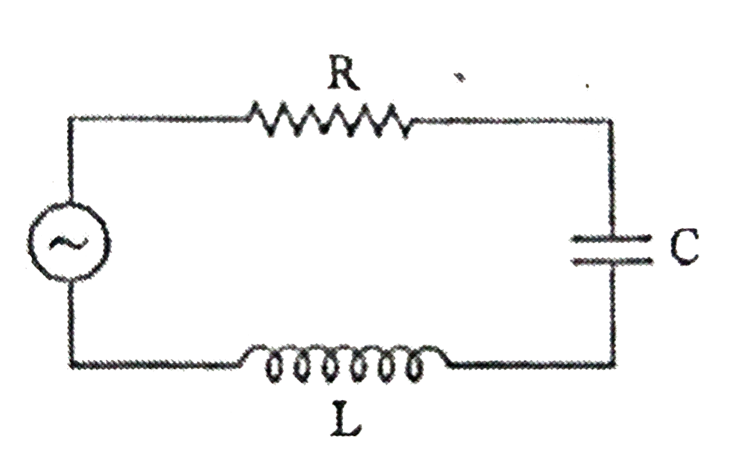
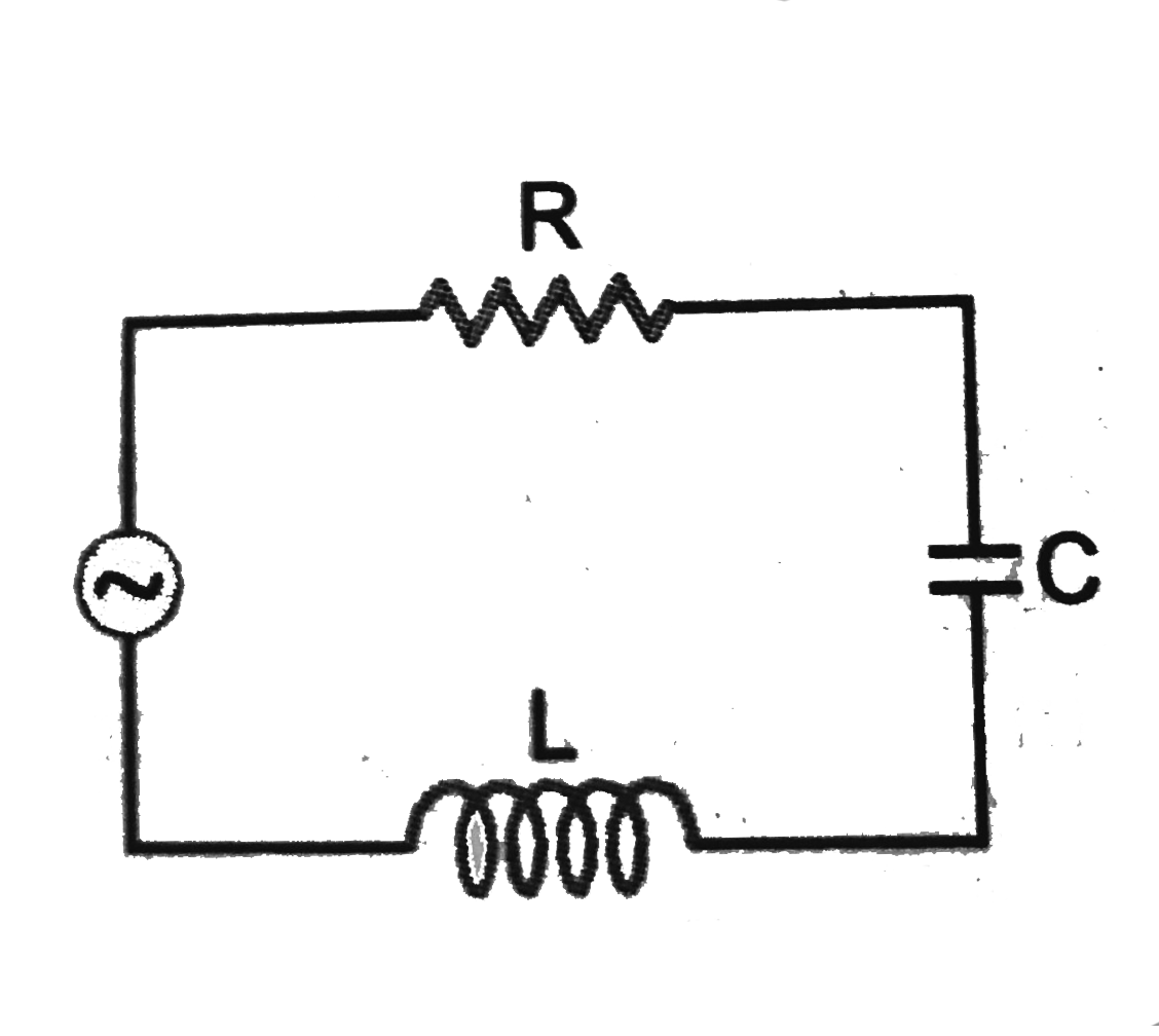
An inductor 200 mH, capacitor 500μF, resistor 10 ohm are connected in series with a 100 V, variable frequency a.c. source. Calculate (i) frequency at which power factor of the circuit is unity (ii) current amplitude at this frequency (iii) Q factor.
To solve the problem step by step, we will calculate the frequency at which the power factor of the circuit is unity, the current amplitude at this frequency, and the Q factor.
Given Data:
- Inductance, L=200mH=200×10−3H
- Capacitance, C=500μF=500×10−6F
- Resistance, R=10Ω
- Voltage, V=100V
Step 1: Frequency at which power factor is unity
The power factor is given by:
Power Factor=cosϕ=RZ
Where Z is the impedance of the circuit. For the power factor to be unity, R=Z.
The impedance Z for an RLC series circuit is given by:
Z=√R2+(XL−XC)2
Where XL=ωL (inductive reactance) and XC=1ωC (capacitive reactance).
For the power factor to be unity:
R=√R2+(XL−XC)2
This implies:
XL−XC=0⇒XL=XC
Substituting the values of XL and XC:
ωL=1ωC
Multiplying both sides by ω:
ω2=1LC
Thus,
ω=1√LC
Substituting the values of L and C:
ω=1√200×10−3×500×10−6
Calculating:
ω=1√100×10−6=110−3=100rad/s
To convert angular frequency ω to frequency f:
f=ω2π=1002π≈15.92Hz
Step 2: Current amplitude at this frequency
At the frequency where the power factor is unity, the impedance Z is equal to the resistance R:
Z=R=10Ω
The current amplitude Imax can be calculated using Ohm's law:
Imax=VR=10010=10A
Step 3: Q factor
The Q factor (quality factor) is given by:
Q=1R√LC
Substituting the values:
Q=110√200×10−3500×10−6
Calculating:
Q=110√200500=110√0.4=110×25=0.4
Final Answers:
1. Frequency at which power factor is unity: f≈15.92Hz
2. Current amplitude at this frequency: Imax=10A
3. Q factor: Q=0.4
- Inductance, L=200mH=200×10−3H
- Capacitance, C=500μF=500×10−6F
- Resistance, R=10Ω
- Voltage, V=100V
The power factor is given by:
Power Factor=cosϕ=RZ
Where Z is the impedance of the circuit. For the power factor to be unity, R=Z.
Z=√R2+(XL−XC)2
Where XL=ωL (inductive reactance) and XC=1ωC (capacitive reactance).
R=√R2+(XL−XC)2
This implies:
XL−XC=0⇒XL=XC
Substituting the values of XL and XC:
ωL=1ωC
Multiplying both sides by ω:
ω2=1LC
Thus,
ω=1√LC
ω=1√200×10−3×500×10−6
Calculating:
ω=1√100×10−6=110−3=100rad/s
f=ω2π=1002π≈15.92Hz
At the frequency where the power factor is unity, the impedance Z is equal to the resistance R:
Z=R=10Ω
The current amplitude Imax can be calculated using Ohm's law:
Imax=VR=10010=10A
The Q factor (quality factor) is given by:
Q=1R√LC
Substituting the values:
Q=110√200×10−3500×10−6
Calculating:
Q=110√200500=110√0.4=110×25=0.4
1. Frequency at which power factor is unity: f≈15.92Hz
2. Current amplitude at this frequency: Imax=10A
3. Q factor: Q=0.4
Topper's Solved these Questions
- XII BOARDSBOOK - XII BOARD PREVIOUS YEAR PAPER ENGLISHCHAPTER - XII BOARDSEXERCISE - SET I
54 Videos
- XII BOARDSBOOK - XII BOARD PREVIOUS YEAR PAPER ENGLISHCHAPTER - XII BOARDSEXERCISE - SET II
8 Videos
- SAMPLE PAPER 2019BOOK - XII BOARD PREVIOUS YEAR PAPER ENGLISHCHAPTER - SAMPLE PAPER 2019EXERCISE - SECTION D
6 Videos
Similar Questions
An inductor 200 mH, capactior 500μF, resistor 10 ohm are connected in series with a 100 V, varialbe frequency a.c. source. Calculate (i) frequency at which power factor of the circuit is unity (ii) current amplitude at this frequency (iii) Q factor.
View SolutionA 100 mH inductor, a 20μF capacitor and a 10 ohm resistor are connected in series to a 100V,50Hz a.c. source. Calculate : (i) Inpendance of the circuit at resonance (ii) Current at resonance (iii) Resonant frequency.
View Solution
Knowledge Check
An inductor 200 mH, capacitor 500μF and resistor 10Ω are connected in series with a 100 V variable frequency ac source. What is the frequency at which the power factor of the circuit is unity?
A10.22HzB12.4HzC19.2HzD15.9Hz
An inductor 20mH, a capacitor 50μF and a resistor 40Ωare connected in series across of emf V=10sin340t. The power loss in A.C. circuit is
View SolutionA series LCR circuit with L=4.0H,C=100μF and R=60Ω is connected to a variable frequency 240 V source. Calculate
(i) angular frequency of the source which drives the circuit in resonance,
(ii) current at the resonating frequency,
(iii) rms potential drop across the inductance at resonance.
View SolutionThe figure shows a series LCR circuit with L=10.0H2,C=40μF,R=60Ω connected to a variable frequency 240 V source. Calculate
(i) The angular frequency of the source which drives the circuit at resonance.
(ii) The current at the resonating frequency.
(iii) The rms potential drop across the capacitor at resonance.

View SolutionFig. shows series LCR circuit with L=5.0H,C=80μF,R=40Ω connected to a variable frequency 240 V source. Calculate
(i) the angular frequency of the source which drives the circuit at resonance.
(ii) Current at the resonating frequency.
(iii) the rms pot. drop across the capacitor at resonance.

View SolutionA satellite is launched into a circular orbit of radius R around the earth while a second satellite is launched into an orbit of radius 1.02R. The percentage difference in the time period is:
View SolutionA 400 Ω resistor, a 3 H inductor and a 5 μF capacitor are connected in series to a 220 V, 50 Hz ac source. Calculate the :
(1) Impedance of the ciruit.
(ii) Current flowing through the circuit.
View SolutionAn inductance L , a capacitor of 20μF and a resistor of 10Ω are connected in series with an AC source of frequency 50 Hz . If the current is in phase with the voltage, then the inductance of the inductor is
View Solution
