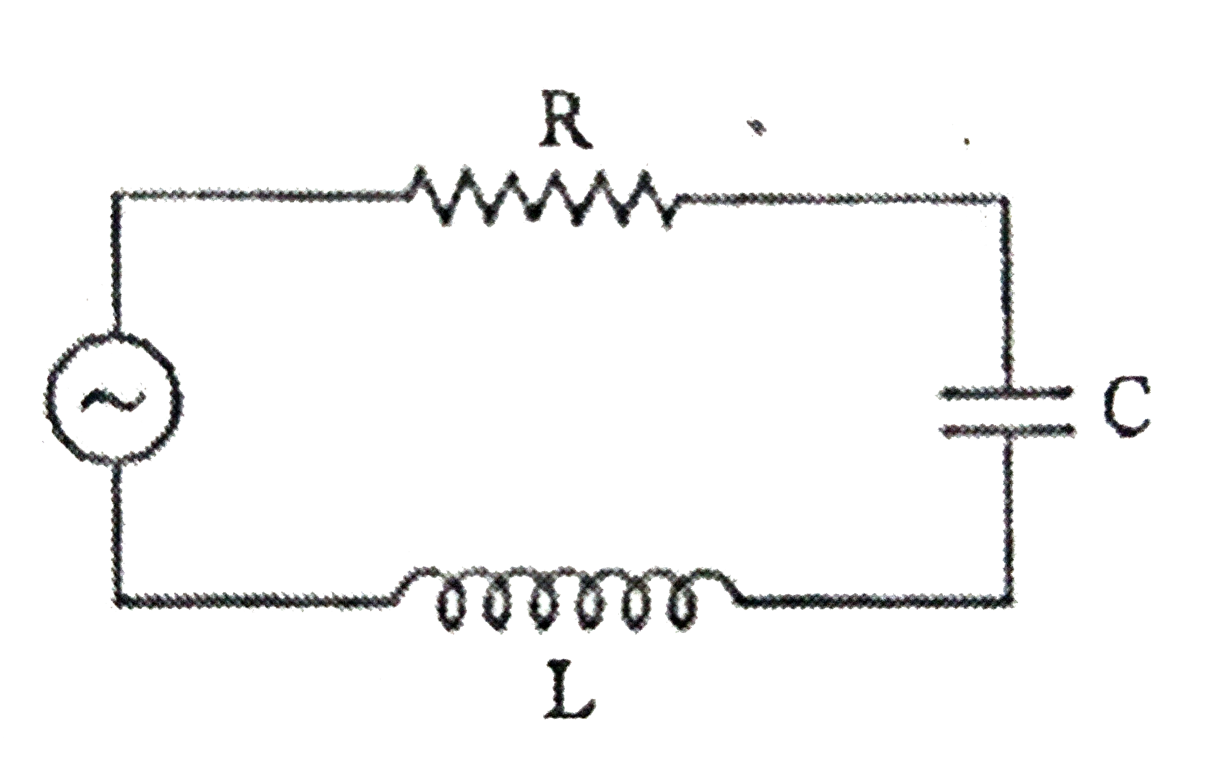
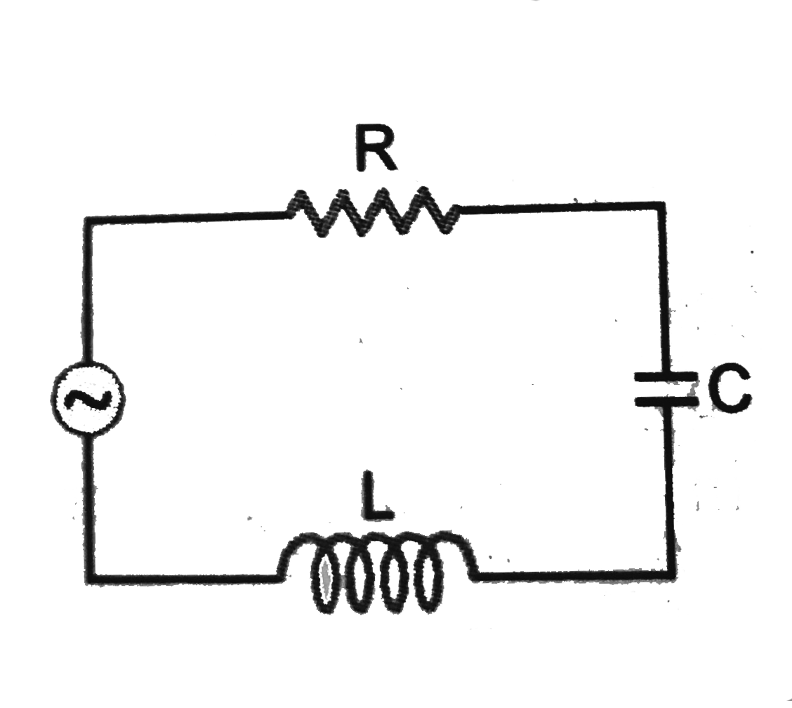
A series LCR circuit with L=4.0H,C=100μF and R=60Ω is connected to a variable frequency 240 V source. Calculate
(i) angular frequency of the source which drives the circuit in resonance,
(ii) current at the resonating frequency,
(iii) rms potential drop across the inductance at resonance.
To solve the problem step by step, we will break down each part of the question regarding the series LCR circuit.
Given Data:
- Inductance (L) = 4.0 H
- Capacitance (C) = 100 µF = 100 × 10^(-6) F
- Resistance (R) = 60 Ω
- RMS Voltage (V) = 240 V
(i) Calculate the angular frequency at resonance
At resonance in an LCR circuit, the inductive reactance (XL) equals the capacitive reactance (XC). This can be expressed mathematically as:
ωL=1ωC
Rearranging gives:
ω2=1LC
Taking the square root:
ω=1√LC
Now substituting the values of L and C:
ω=1√4×100×10−6
Calculating the denominator:
4×100×10−6=4×0.0001=0.0004
Thus:
ω=1√0.0004=10.02=50rad/s
(ii) Calculate the current at the resonating frequency
At resonance, the impedance (Z) of the circuit is equal to the resistance (R):
Z=R=60Ω
The RMS current (I) can be calculated using Ohm's law:
I=VZ
Substituting the values:
I=240V60Ω=4A
(iii) Calculate the RMS potential drop across the inductance at resonance
The potential drop across the inductance (V_L) can be calculated using:
VL=I⋅XL
Where XL=ωL. We already found ω=50rad/s:
Calculating XL:
XL=50×4=200Ω
Now substituting into the equation for VL:
VL=4A×200Ω=800V
Final Answers:
(i) Angular frequency at resonance: 50 rad/s
(ii) Current at resonating frequency: 4 A
(iii) RMS potential drop across the inductance at resonance: 800 V
- Inductance (L) = 4.0 H
- Capacitance (C) = 100 µF = 100 × 10^(-6) F
- Resistance (R) = 60 Ω
- RMS Voltage (V) = 240 V
(i) Angular frequency at resonance: 50 rad/s
(ii) Current at resonating frequency: 4 A
(iii) RMS potential drop across the inductance at resonance: 800 V
Similar Questions
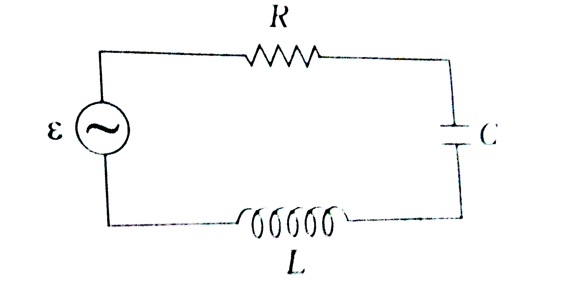
The figure shows a series LCR circuit with L=10.0H2,C=40μF,R=60Ω connected to a variable frequency 240 V source. Calculate
(i) The angular frequency of the source which drives the circuit at resonance.
(ii) The current at the resonating frequency.
(iii) The rms potential drop across the capacitor at resonance.

View SolutionFig. shows series LCR circuit with L=5.0H,C=80μF,R=40Ω connected to a variable frequency 240 V source. Calculate
(i) the angular frequency of the source which drives the circuit at resonance.
(ii) Current at the resonating frequency.
(iii) the rms pot. drop across the capacitor at resonance.

View Solution
Knowledge Check
Figure shows a series LCR circuit connected to a variable frequency 230 V source.

The source frequency which drives the circuit the circuit in resonance isA4 HzB5 HzC6 HzD8 HzThe resonant frequency of a series LCR circuit with L=2.0H,C=32μF and R=10Ω is
A20 HzB30 HzC40 HzD50 HzA series LCR circuit with R=20Ω,L=1.5H and C=35μF is connected to a variable frequency 200V ac supply. When the frequency of the supply equals the natural frequency of the circuit, what is the average power in kW transferred to the circuit in one complete cycle?
A200 WB2000 WC100 WD4000 W
In an L C R circuit having L = 8 H, C = 0 5μF and R=100Ω in series, the resonance frequency in rad/s is
View SolutionAn inductor 200 mH, capacitor 500μF, resistor 10 ohm are connected in series with a 100 V, variable frequency a.c. source. Calculate (i) frequency at which power factor of the circuit is unity (ii) current amplitude at this frequency (iii) Q factor.
View SolutionAn inductor 200 mH, capactior 500μF, resistor 10 ohm are connected in series with a 100 V, varialbe frequency a.c. source. Calculate (i) frequency at which power factor of the circuit is unity (ii) current amplitude at this frequency (iii) Q factor.
View SolutionA series LCR circuit with R=20Ω,L=1.5H and C=35μF is connected to a variable frequency 200V ac supply. When the frequency of the supply equals the natural frequency of the circuit, what is the average power in kW transferred to the circuit in one complete cycle?
View SolutionFigure here, shows a series L-C-R circuit connected to a variable frequency 230 V source. L = 5.0H, C = 80μF and r =40Ω
(a) Determine the source frequency which drives the circuit in resonance.
(b) Obtain the impedance of the circuit and the amplitude of current at the resonating frequency.
(c) Determine the rms potential drops across the three elements of the circuit. show that the potential drop across the L-C combination is zero at the resonating frequency.

View Solution
