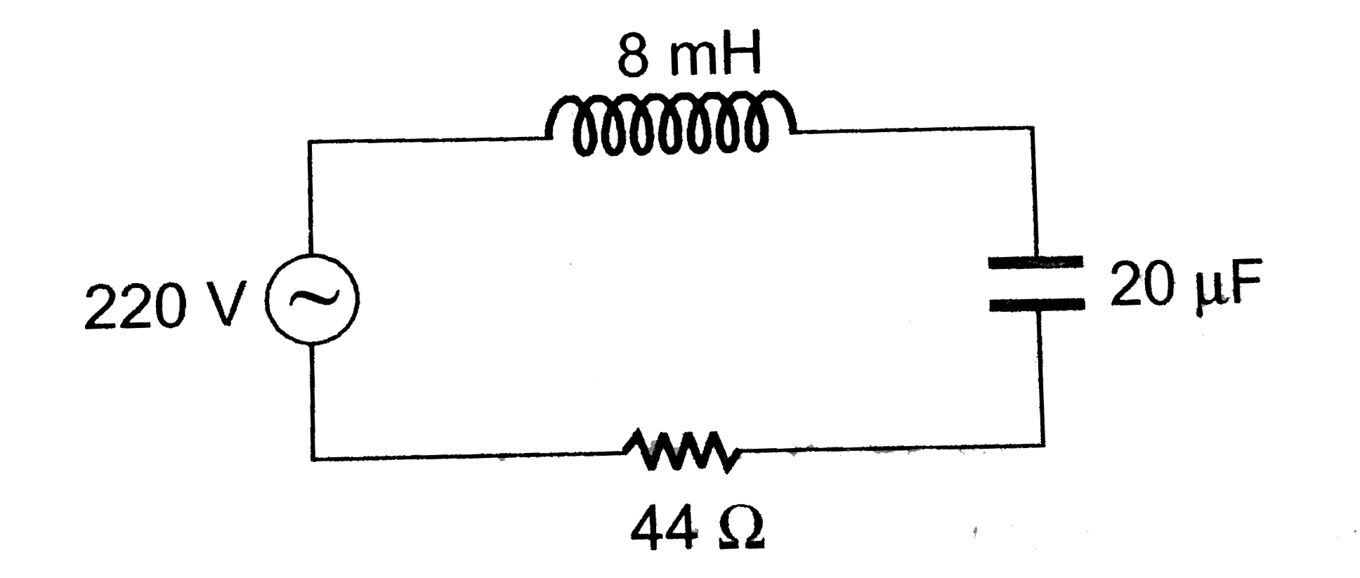
When the frequency of the AC source in an LCR circuit equals the resonant frequency, the reactance of the circuit is zero. Does it mean that there is no current through the inductor or the capacitor?
To solve the question, let's break it down step by step:
Step 1: Understanding Resonance in an LCR Circuit
In an LCR circuit (which consists of an inductor (L), a capacitor (C), and a resistor (R)), resonance occurs when the inductive reactance (X_L) equals the capacitive reactance (X_C). This condition can be expressed mathematically as:
XL=XC
At resonance, the total reactance (X) of the circuit is zero:
X=XL−XC=0
Step 2: Reactance Values
The inductive reactance (X_L) and capacitive reactance (X_C) are given by:
XL=ωL
XC=1ωC
Where:
- ω is the angular frequency of the AC source.
At resonance:
ωL=1ωC
Step 3: Impedance at Resonance
The impedance (Z) of the circuit at resonance can be calculated as:
Z=√R2+X2
Since the reactance (X) is zero at resonance:
Z=√R2+02=R
Step 4: Current in the Circuit
The current (I) through the circuit can be expressed using Ohm's law:
I=VrmsZ
Substituting the impedance at resonance:
I=VrmsR
This shows that the current is determined by the voltage and resistance.
Step 5: Current Through Inductor and Capacitor
Even though the total reactance is zero at resonance, it does not mean that there is no current through the inductor and capacitor. Instead, the current through the inductor and capacitor is equal in magnitude but opposite in phase. This means:
- The current through the inductor (I_L) and the current through the capacitor (I_C) are equal:
IL=IC=I
However, they are 180 degrees out of phase with each other, resulting in their effects canceling out in terms of net reactance.
Conclusion
Thus, at the resonant frequency, while the total reactance is zero, there is still a current flowing through both the inductor and the capacitor. The current is not zero; rather, it is the phase difference between the currents in the inductor and capacitor that leads to the cancellation of their reactance.
Summary
1. At resonance, XL=XC leading to zero total reactance.
2. Impedance at resonance is equal to the resistance R.
3. Current through the circuit is I=VrmsR.
4. There is still current through both the inductor and capacitor, but they are 180 degrees out of phase.
In an LCR circuit (which consists of an inductor (L), a capacitor (C), and a resistor (R)), resonance occurs when the inductive reactance (X_L) equals the capacitive reactance (X_C). This condition can be expressed mathematically as:
XL=XC
At resonance, the total reactance (X) of the circuit is zero:
X=XL−XC=0
The inductive reactance (X_L) and capacitive reactance (X_C) are given by:
XL=ωL
XC=1ωC
Where:
- ω is the angular frequency of the AC source.
ωL=1ωC
The impedance (Z) of the circuit at resonance can be calculated as:
Z=√R2+X2
Since the reactance (X) is zero at resonance:
Z=√R2+02=R
The current (I) through the circuit can be expressed using Ohm's law:
I=VrmsZ
Substituting the impedance at resonance:
I=VrmsR
This shows that the current is determined by the voltage and resistance.
Even though the total reactance is zero at resonance, it does not mean that there is no current through the inductor and capacitor. Instead, the current through the inductor and capacitor is equal in magnitude but opposite in phase. This means:
- The current through the inductor (I_L) and the current through the capacitor (I_C) are equal:
IL=IC=I
However, they are 180 degrees out of phase with each other, resulting in their effects canceling out in terms of net reactance.
Thus, at the resonant frequency, while the total reactance is zero, there is still a current flowing through both the inductor and the capacitor. The current is not zero; rather, it is the phase difference between the currents in the inductor and capacitor that leads to the cancellation of their reactance.
1. At resonance, XL=XC leading to zero total reactance.
2. Impedance at resonance is equal to the resistance R.
3. Current through the circuit is I=VrmsR.
4. There is still current through both the inductor and capacitor, but they are 180 degrees out of phase.
Topper's Solved these Questions
Similar Questions
Knowledge Check
At resonance frequency the impedance in series LCR circuit is
AmaximumBminimumCzeroDinfinityAt resonant frequency the current amplitude in series LCR circuit is
AmaximumBminimumCzeroDinfinityTo reduce the resonant frequency in an LCR series circuit with a generator
Athe generator frequency should be reduced.Banother capacitor should be added in parallel to the first.Cthe iron core of the inductor should be removed.Ddielectric in the capacitor should be removed.
When the frequency of AC is doubled, the impedance of an LCR series circuit
View SolutionIn a series LCR circuit, the frequency of the source is more than resonance frequency. The current in the circuit leads the voltage in phases(True/false).
View SolutionFor the series LCR circuit shown in the figure, what is the resonance frequency and the amplitude of the current at the resonating frequency

View SolutionFor the series LCR circuit shown in the figure, what is the resonance frequency and the amplitude of the current at the resonating frequency

View SolutionIn a series LCR circuit, obtain an expression for the resonant frequency.
View Solution
