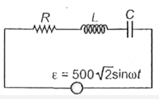
Can the peak voltage across the inductor be greater than the peak voltage of the source in an LCR circuit?
To determine whether the peak voltage across the inductor can be greater than the peak voltage of the source in an LCR circuit, we can follow these steps:
1. Understand the LCR Circuit:
An LCR circuit consists of an inductor (L), a capacitor (C), and a resistor (R) connected in series. The source voltage is typically an alternating current (AC) voltage.
2. Impedance in LCR Circuit:
The impedance (Z) of an LCR circuit is given by the formula:
Z=√R2+(XC−XL)2
where XC is the capacitive reactance and XL is the inductive reactance.
3. Current in the Circuit:
The current (I) in the circuit can be expressed as:
I=I0sin(ωt+ϕ)
where I0 is the peak current, ω is the angular frequency, and ϕ is the phase difference.
4. Voltage Across the Inductor:
The voltage across the inductor (V_L) can be calculated using:
VL=LdIdt
Substituting I:
VL=Lddt(I0sin(ωt+ϕ))
This gives:
VL=LI0ωcos(ωt+ϕ)
5. Peak Voltage Across the Inductor:
The peak voltage across the inductor occurs when cos(ωt+ϕ)=1:
VL,peak=LI0ω
6. Relate Peak Current to Source Voltage:
The peak current I0 can be related to the peak voltage of the source E0 using:
I0=E0Z
Substituting this into the expression for peak voltage across the inductor:
VL,peak=L(E0Z)ω
7. Condition for VL to be Greater than E0:
For the peak voltage across the inductor to be greater than the peak voltage of the source:
L(E0Z)ω>E0
Simplifying this gives:
LωZ>1
This can be rearranged to show:
Lω>Z
8. Resonance Condition:
At resonance, the impedance Z is minimized (equal to R). If L/R>1, then it is possible for the peak voltage across the inductor to exceed the peak voltage of the source.
Conclusion:
Yes, the peak voltage across the inductor can be greater than the peak voltage of the source in an LCR circuit under certain conditions, particularly when the ratio L/R is greater than 1.
An LCR circuit consists of an inductor (L), a capacitor (C), and a resistor (R) connected in series. The source voltage is typically an alternating current (AC) voltage.
The impedance (Z) of an LCR circuit is given by the formula:
Z=√R2+(XC−XL)2
where XC is the capacitive reactance and XL is the inductive reactance.
The current (I) in the circuit can be expressed as:
I=I0sin(ωt+ϕ)
where I0 is the peak current, ω is the angular frequency, and ϕ is the phase difference.
The voltage across the inductor (V_L) can be calculated using:
VL=LdIdt
Substituting I:
VL=Lddt(I0sin(ωt+ϕ))
This gives:
VL=LI0ωcos(ωt+ϕ)
The peak voltage across the inductor occurs when cos(ωt+ϕ)=1:
VL,peak=LI0ω
The peak current I0 can be related to the peak voltage of the source E0 using:
I0=E0Z
Substituting this into the expression for peak voltage across the inductor:
VL,peak=L(E0Z)ω
For the peak voltage across the inductor to be greater than the peak voltage of the source:
L(E0Z)ω>E0
Simplifying this gives:
LωZ>1
This can be rearranged to show:
Lω>Z
At resonance, the impedance Z is minimized (equal to R). If L/R>1, then it is possible for the peak voltage across the inductor to exceed the peak voltage of the source.
Yes, the peak voltage across the inductor can be greater than the peak voltage of the source in an LCR circuit under certain conditions, particularly when the ratio L/R is greater than 1.
Topper's Solved these Questions
Similar Questions
Knowledge Check
V(rms )= 220volt , the peak voltage of the source is
A305 VB310 VC311 VD315 V
(a) In a series LCR circuit connected across an AC source of variable frequency, obtain the expression for its impedance and draw a plot showing its variation with frequency of the AC source.
(b) What is the phase difference between the voltages across inductor and the capacitor at resonance in the LCR circuit ?
(c ) When and inductor is connected to a 200 V DC voltage, a current of 1Aflows trough it. when the same inductor is connected to a 200 V, 50 Hz AC source, only 0.5 A current flows. Explain, why ? Also, calculate the self inductance of the inductor.
View SolutionIn a series LCR circuit with an AC source, R=300Ω,C=20μF,L=1.0henry,εrms=50V and v=50πHz. Find (a) the rms current in the circuit and (b) the rms potential differences across the capacitor, the resistor and the inductor. Note that the sum of the rms potential differences across the three elements is greater than the rms voltage of the source.
View SolutionIn a series LCR circuit with an AC source, R=300Ω,C=20μF,L=1.0henry,εrms=50V and v=50πHz. Find (a) the rms current in the circuit and (b) the rms potential differences across the capacitor, the resistor and the inductor. Note that the sum of the rms potential differences across the three elements is greater than the rms voltage of the source.
View SolutionAssertion: In an AC circuit, potential difference across the capacitor may be greater than the applied voltage.
Reason : VC=IXC, wheereas V=IZ and XC can be greater than Z also.
View SolutionWhat is the peak value of the voltage of a 220V ac line?
View SolutionIn a series RLC circuit the r.m.s. voltage across the resistor and the inductor are respectively 400 V and 700 V. If the equation for the applied Voltage is ε=500√2sinωt. then the peak voltage across the capacitor is

View SolutionAn LCR series circuit is connected to an oscillator (AC supply) having RMS voltage 200 V. If the RMS voltages across resistor, inductor and capacitor are equal, then RMS voltage across the resistor would be
View Solution
