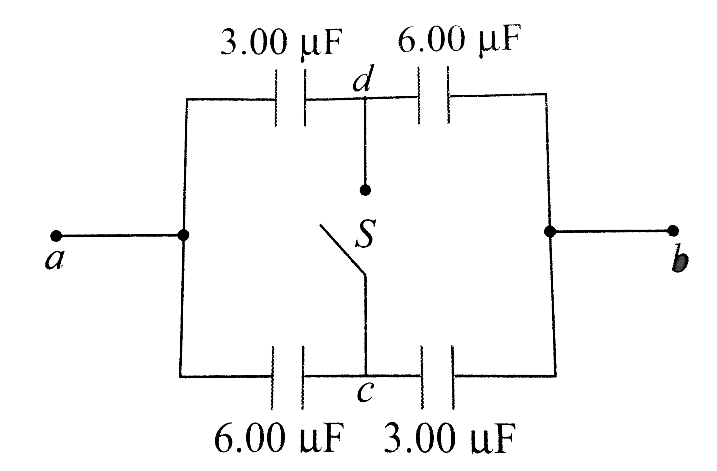
The capacitors in figure are initially uncharged and are connected as in the diagram with switch S open. The applied potential difference is

What is the potential difference across each capacitor after switch S is closed
100 V
180 V
200 V
300 V
The correct Answer is:B
Topper's Solved these Questions
- CAPACITORS BOOK - AAKASH SERIESCHAPTER - CAPACITORS EXERCISE - PRACTICE SHEET (EXERCISE - III) (LEVEL - I (MAIN)) (Straight Objective Type Questions)
5 Videos
- CAPACITORS BOOK - AAKASH SERIESCHAPTER - CAPACITORS EXERCISE - PRACTICE SHEET (EXERCISE - III) (LEVEL - II (ADVANCED)) (More than One correct answer Type Questions)
7 Videos
- CAPACITORS BOOK - AAKASH SERIESCHAPTER - CAPACITORS EXERCISE - PRACTICE SHEET (EXERCISE - II) (LEVEL - II (MAIN)) (Straight Objective Type Questions)
6 Videos
- ATOMSBOOK - AAKASH SERIESCHAPTER - ATOMSEXERCISE - PRACTICE EXERCISE
21 Videos
- COMMUNICATION SYSTEM BOOK - AAKASH SERIESCHAPTER - COMMUNICATION SYSTEM EXERCISE - LECTURE SHEET (LEVEL - I) (MAIN) (EXERCISE - IV) (Straight Objective & More than one Correct Answer Type Questions)
20 Videos
Similar Questions
The capacitors in are initially uncharged and are connected as in the diagram with switch S open. The applied potential difference is Vab=+360V.
 .
.
a. What is the potential difference Vcd
b What is the potential difference across each capacitor after switch S is closed?
c. How much charge will flow through the switch after it is closed?
View SolutionThe capacitors in are initially uncharged and are cannected as in the diagram with switch S open. The applied potential differnce is Vab=+360V.
 .
.
a. What is the potential differnce Vcd
b What is the potential deffernce across each capacitor afrer switch S is closed?
c. How much charge will flow through the awitch after it is closed?
View Solution
Knowledge Check
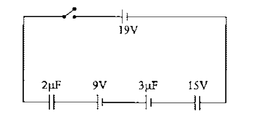
The two capacitors in the circuit shown in figure are initially uncharged and then connected as shown and switch is closed. What is the potential difference across 3μF capacitor?
 A30VB10VC25VDNone of these
Two capacitors of capacitances 10μFand20μF are connected in series across a potential difference of 100V. The potential difference across each capacitor is respectively
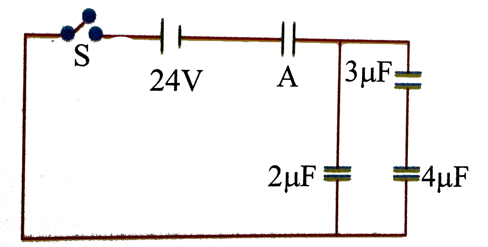
A66.67 V, 33.33 VB60 V, 40 VC50 V, 50 VD90 V, 10 VFour capacitor and a battery of emf24V are connected as shown in the figure. Initially, S is open and the capacitors are uncharged. After S is closed and steady state is attained, the potential difference across the 4μf capacitor is 7.5V. The capacitance in μf of the capacitor A is.
 .A5B7C8D10
A 220 V A supply is connected between points A and B in figure. What will be the potential difference V across the capacitor?
View SolutionIn the circuit of figure, the battery emf is ε the resitance is R and the capacitance is C. The switch S is closed for a long time interval, and zero potential difference is measured across the capacitor

After the switch is opened. the potential difference across the capacitor reaches a maximum value of ΔV. What is the value of the inductance?
View SolutionIn the circuit shown in fig, switch S was closed for long time. At time t-0, the switch is opened again. The maximum potential difference across the plates of the capacitor after the switch is opened is

View SolutionIn the circuit of figure, the battery emf is g the resitance is R and the capacitance is C. The switch S is closed for a long time interval, and zero potential difference is measured across the capacitor

After the switch is opened. the potential difference across the capacitor reaches a maximum value of ΔV. What is the value of the inductance?
View SolutionIn the circuit shown in fig, switch S was closed for long time. At time t-0, teh switch is opened again. The maximum potential difference across teh plates of the capacitor after the switch is opened is

View Solution
