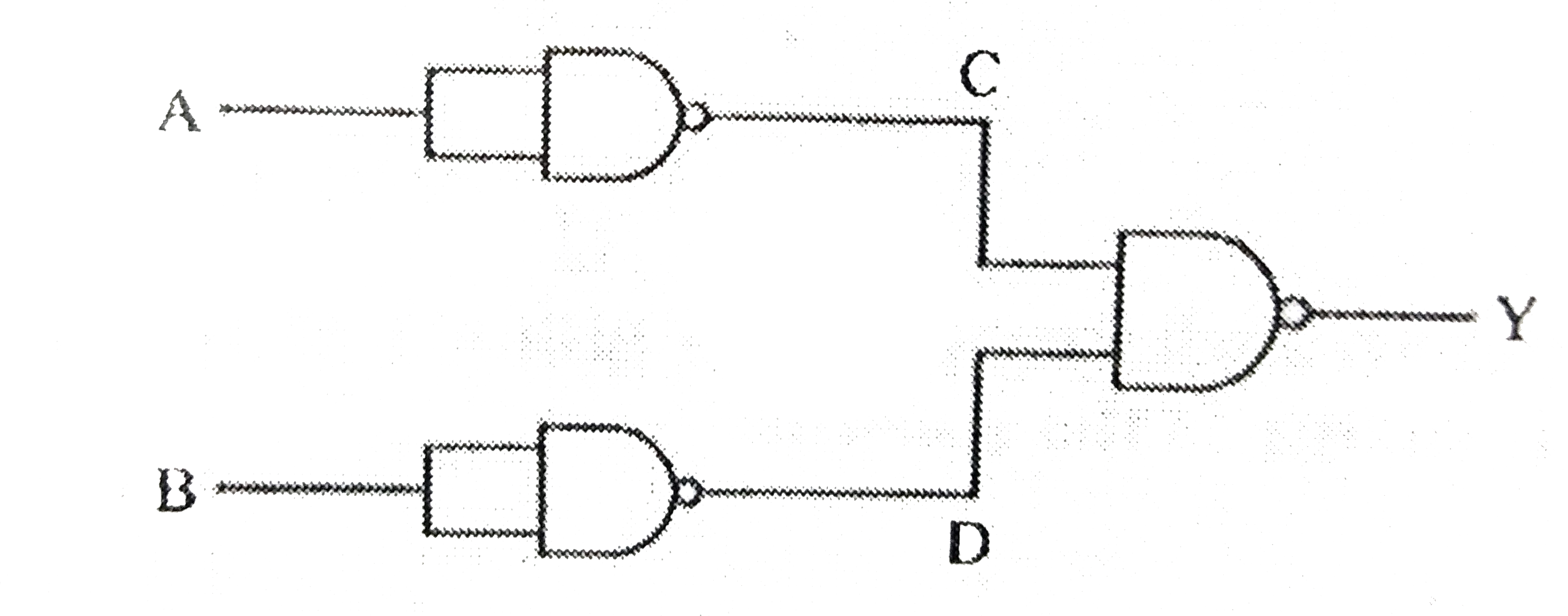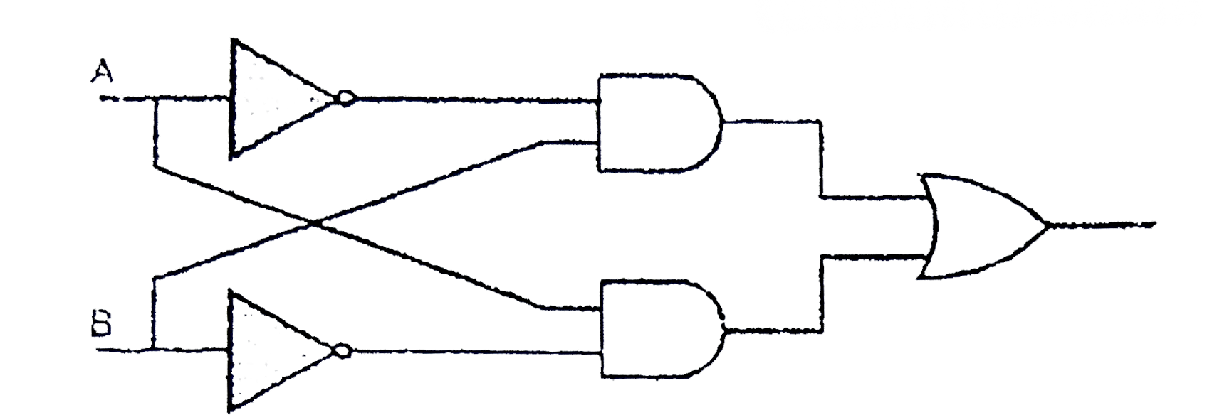
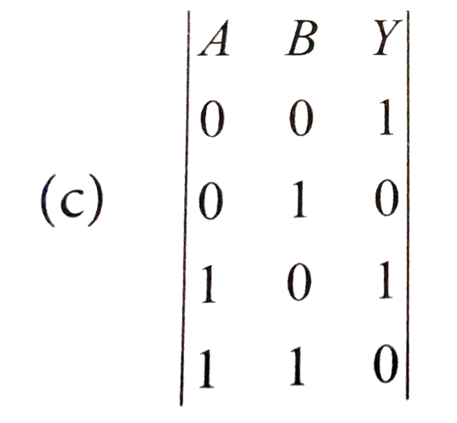
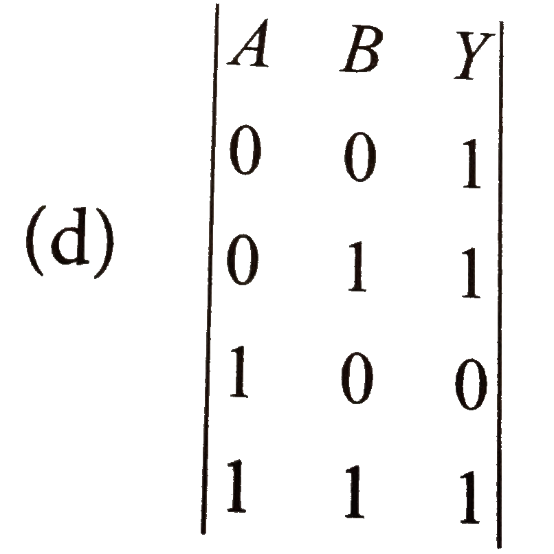
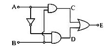
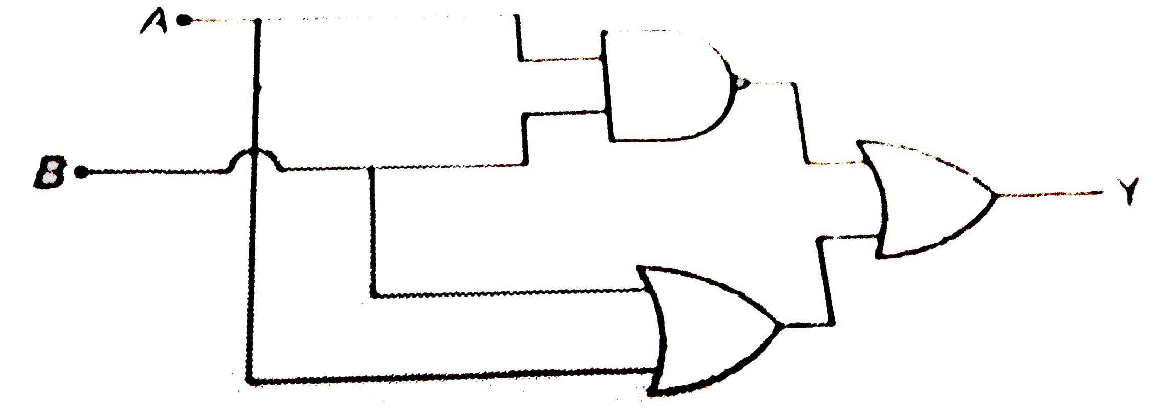
The truth table of the logic circuit shown-
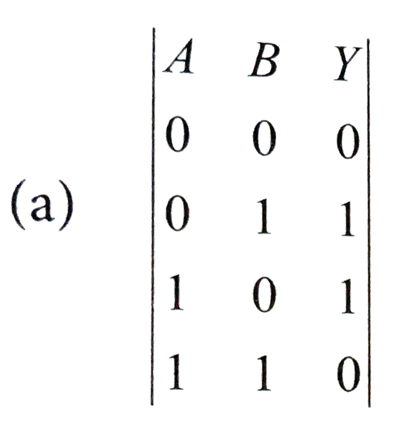
A
B
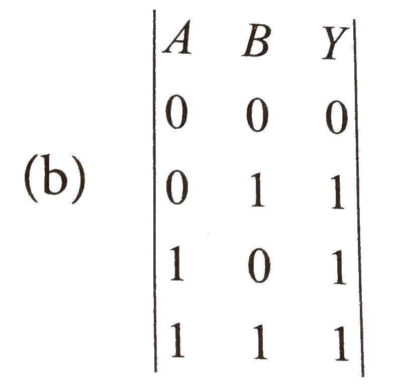
C
D
Video Solution
Text Solution
The correct Answer is:A

Y=¯¯¯A.B+A.¯¯¯B
The truth table for the given logic circuit is

|
Topper's Solved these Questions
- SEMICONDUCTOR ELECTRONICS : MATERIALS , DEVICES AND SIMPLE CIRCUITS BOOK - NCERT FINGERTPS ENGLISHCHAPTER - SEMICONDUCTOR ELECTRONICS : MATERIALS , DEVICES AND SIMPLE CIRCUITS EXERCISE - HOTS
8 Videos
- SEMICONDUCTOR ELECTRONICS : MATERIALS , DEVICES AND SIMPLE CIRCUITS BOOK - NCERT FINGERTPS ENGLISHCHAPTER - SEMICONDUCTOR ELECTRONICS : MATERIALS , DEVICES AND SIMPLE CIRCUITS EXERCISE - NCERT
8 Videos
- RAY OPTICS AND OPTICAL INSTRUMENTSBOOK - NCERT FINGERTPS ENGLISHCHAPTER - RAY OPTICS AND OPTICAL INSTRUMENTSEXERCISE - NCERT Exemplar
11 Videos
- WAVE OPTICSBOOK - NCERT FINGERTPS ENGLISHCHAPTER - WAVE OPTICSEXERCISE - Assertion And Reason
15 Videos
Similar Questions
Knowledge Check
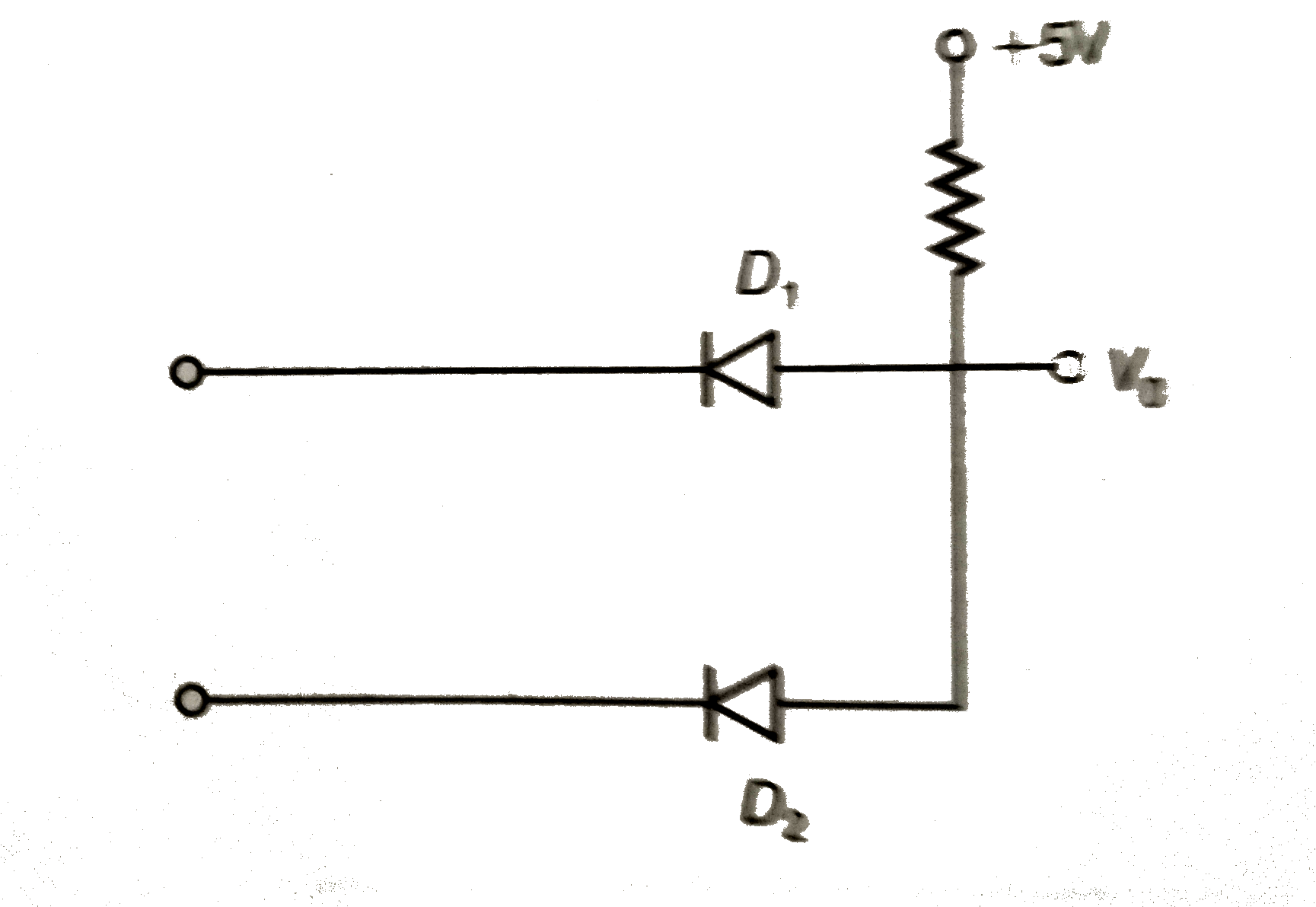
Write the truth table for the circuit shown in figure given below. Name the gate that the circuit resembles.
 ANANDBANDCORDNOR
Truth table for the given circuit is
View SolutionThe truth table for the circuit shown in the figure is
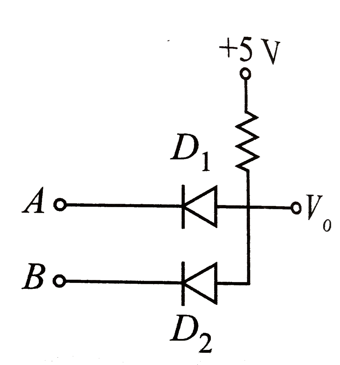
View SolutionStudy the circuits shown in the figure. Name the gate that the given circuit resembles.
View SolutionWrite the truth table of the following circuit. Name the gate represented by this circuit.

View SolutionThe output (X) of the logic circuit shown in figure will be

View SolutionThe outpout Y of the logic circuit shown in figure is best represented as
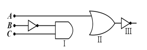
View SolutionThe output of the given logic circuit is
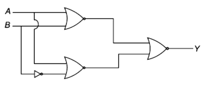
View Solution

