The output (X) of the logic circuit shown in figure will be

A
X=¯¯¯¯¯¯¯A.¯¯¯¯¯¯B
B
X=¯¯¯¯¯¯¯¯A.B
C
X=A.B
D
A=¯¯¯¯¯¯¯¯¯¯¯A+B
Video Solution
Text Solution
The correct Answer is:C
|
Answer
Step by step video & image solution for The output (X) of the logic circuit shown in figure will be by Physics experts to help you in doubts & scoring excellent marks in Class 12 exams.
Updated on:21/07/2023Similar Questions
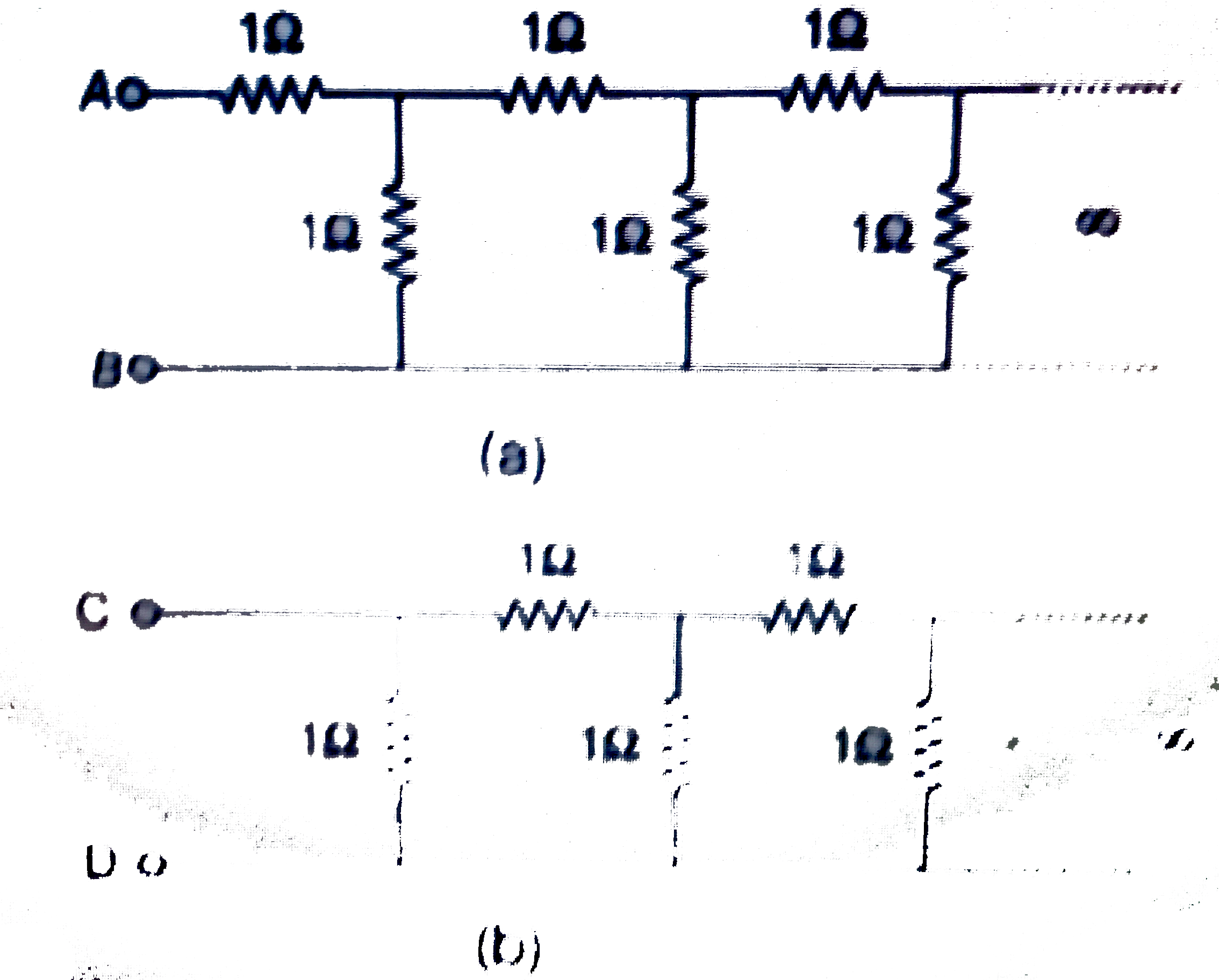
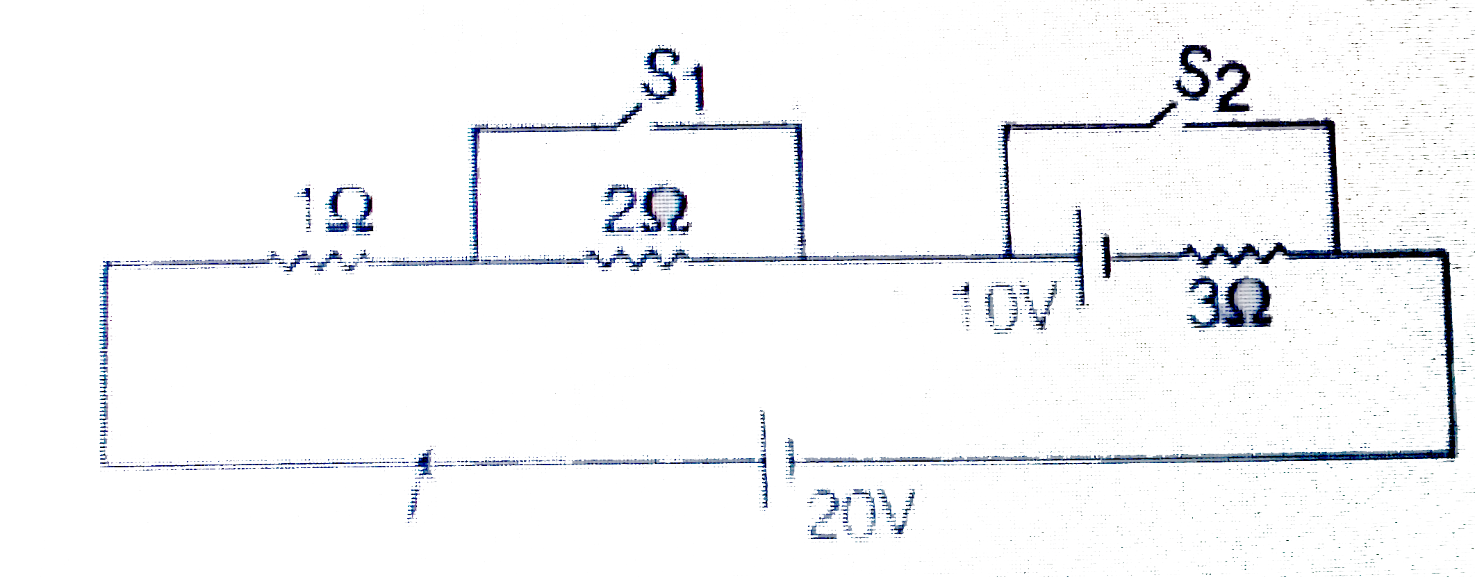
In the two circuits shown in figure
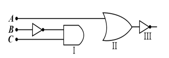
View SolutionThe outpout Y of the logic circuit shown in figure is best represented as
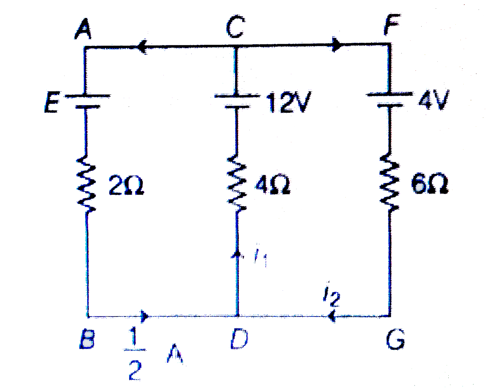
View SolutionIn the circuit shown in figure
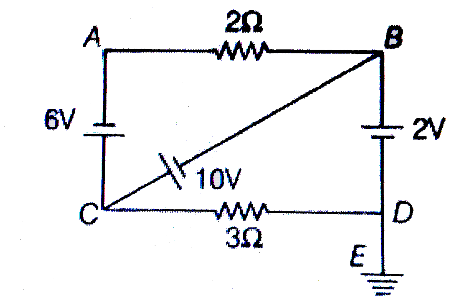
View SolutionIn the circuit shown in figure
View SolutionIn the circuit shown in figure
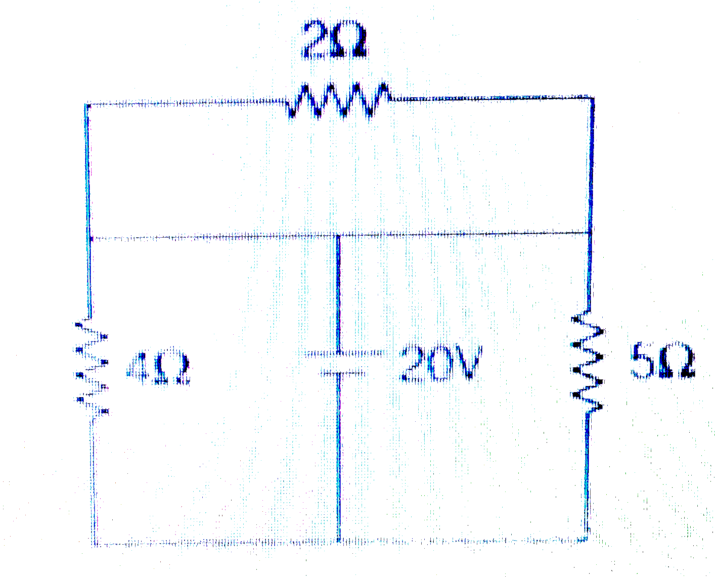
View SolutionIn the circuit shown in figure
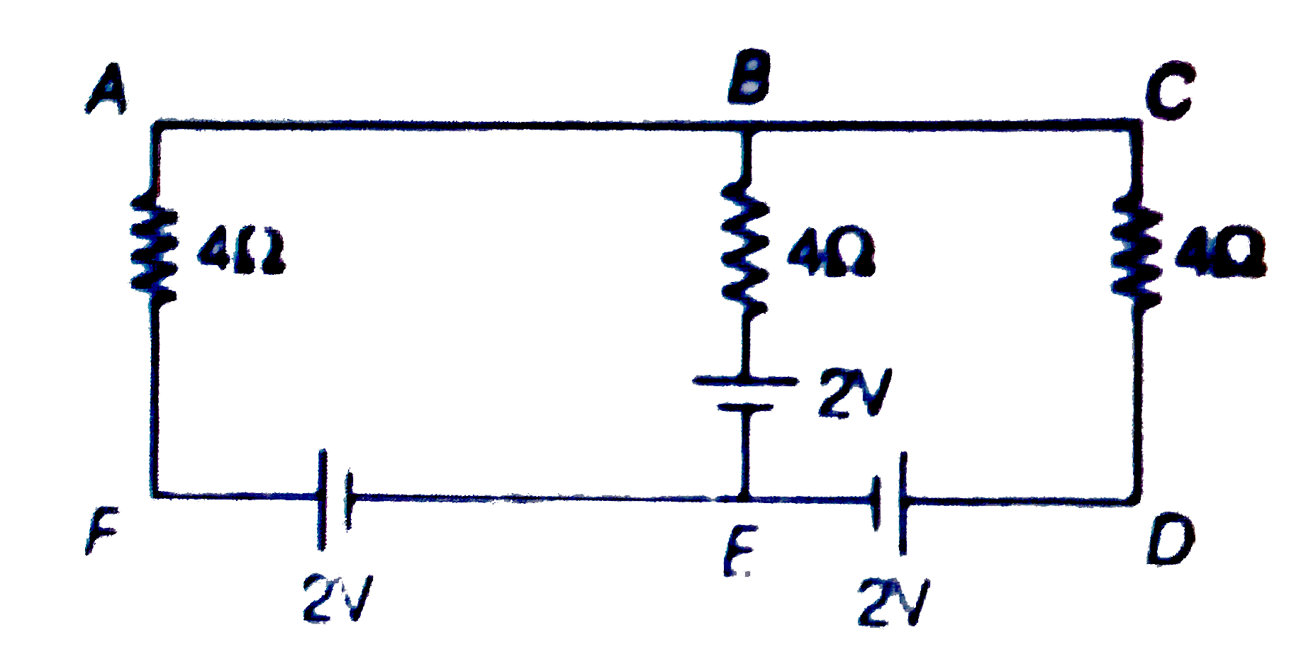
View SolutionIn the circuit shown in figure
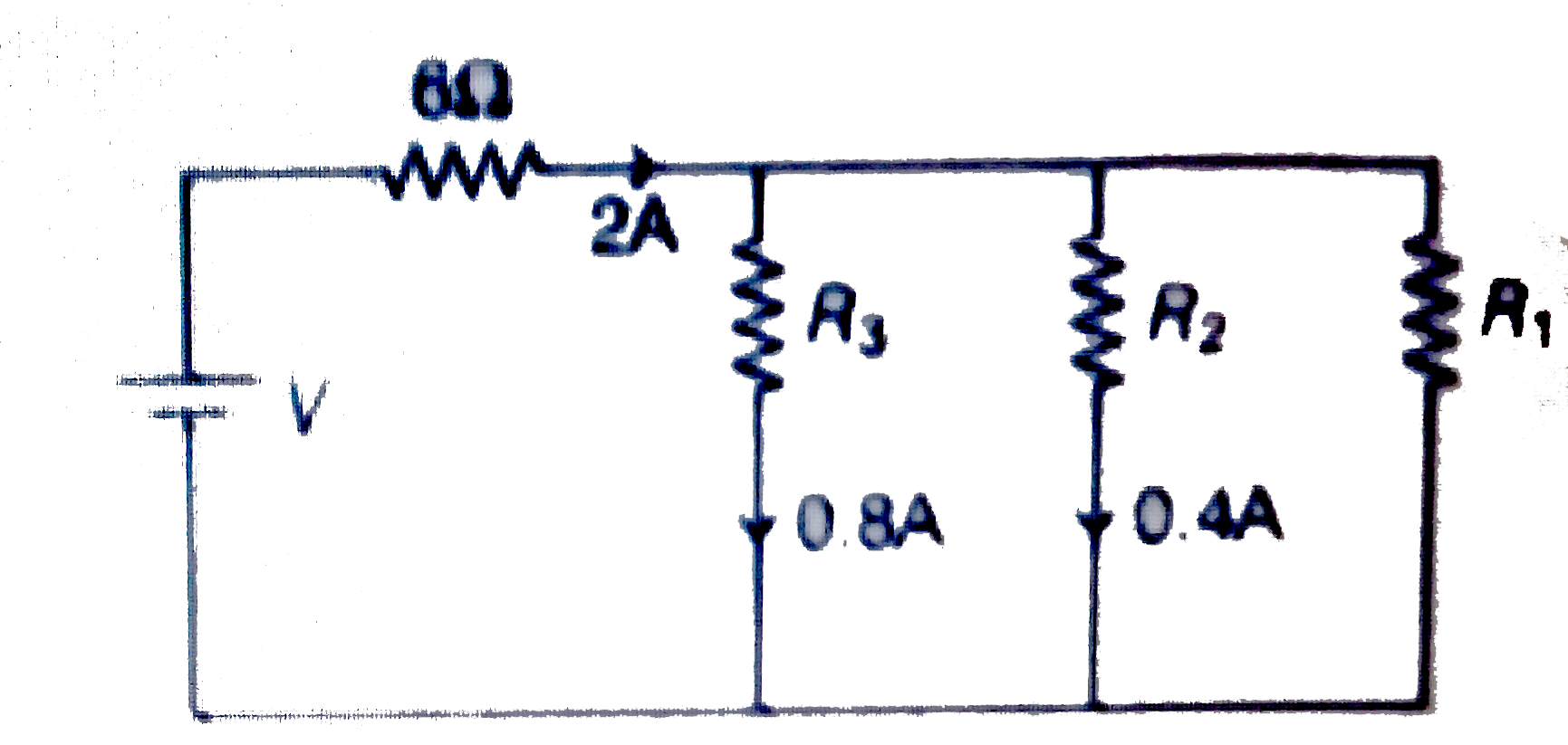
View SolutionIn the circuit shown in figure
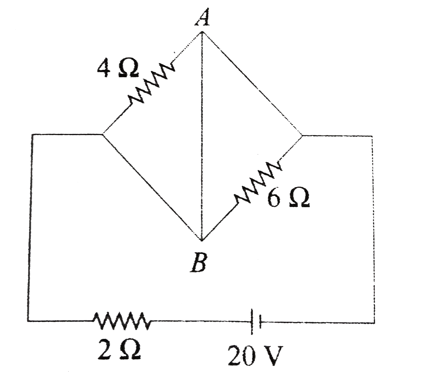
View SolutionIn the circuit shown in figure
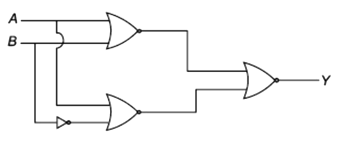
View SolutionThe output of the given logic circuit is
View Solution
