Find maximum voltage across AB in the circuit shown in figure. Assume that the diode is ideal.
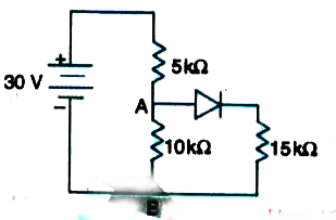 Solution in Telugu
16.32V
Topper's Solved these Questions
- SEMICONDUCTOR DEVICESBOOK - AAKASH SERIESCHAPTER - SEMICONDUCTOR DEVICESEXERCISE - Problems (LEVEL-II)
7 Videos
- SEMICONDUCTOR DEVICESBOOK - AAKASH SERIESCHAPTER - SEMICONDUCTOR DEVICESEXERCISE - EXAMPLES
56 Videos
- SEMICONDUCTOR DEVICESBOOK - AAKASH SERIESCHAPTER - SEMICONDUCTOR DEVICESEXERCISE - Exercise (very Short answer questions)
11 Videos
- RAY OPTICSBOOK - AAKASH SERIESCHAPTER - RAY OPTICSEXERCISE - PROBLEMS ( LEVEL-II)
50 Videos
- UNITS AND MEASUREMENTBOOK - AAKASH SERIESCHAPTER - UNITS AND MEASUREMENTEXERCISE - PRACTICE EXERCISE
45 Videos
Similar Questions
A n-type silicon sample of width 4×10⁻³m, thickness 25×10−5m and length 6×10⁻²m carries a current of 4.8 mA when the voltage is applied across the length of the sample. If the free electron density is 1022m−3, then find how much time does it take for the electrons to travel the full length of the sample? Given that charge on an electron e=1.6×10⁻¹⁹C
View SolutionThe energy of a photon of sodium light (λ=589nm) equal to the band gap of a semiconducing material .
Find the minimum energy E required to create a hole -electron pair.
View SolutionWhat are intrinsic and extrinsic seniconductors?
View SolutionTwo plane mirrors are combined to each other such that one is in y-z plane and the other is in X-z plane. A ray of light travelling along a vector ˆi+ˆi+ˆk is incident on the first mirror. Find the unit vector in the direction of emergent ray after successive reflections through both the mirrors.
View SolutionThe ratio of S.I. unit of universal gravitational constant to C.G.S. unit is
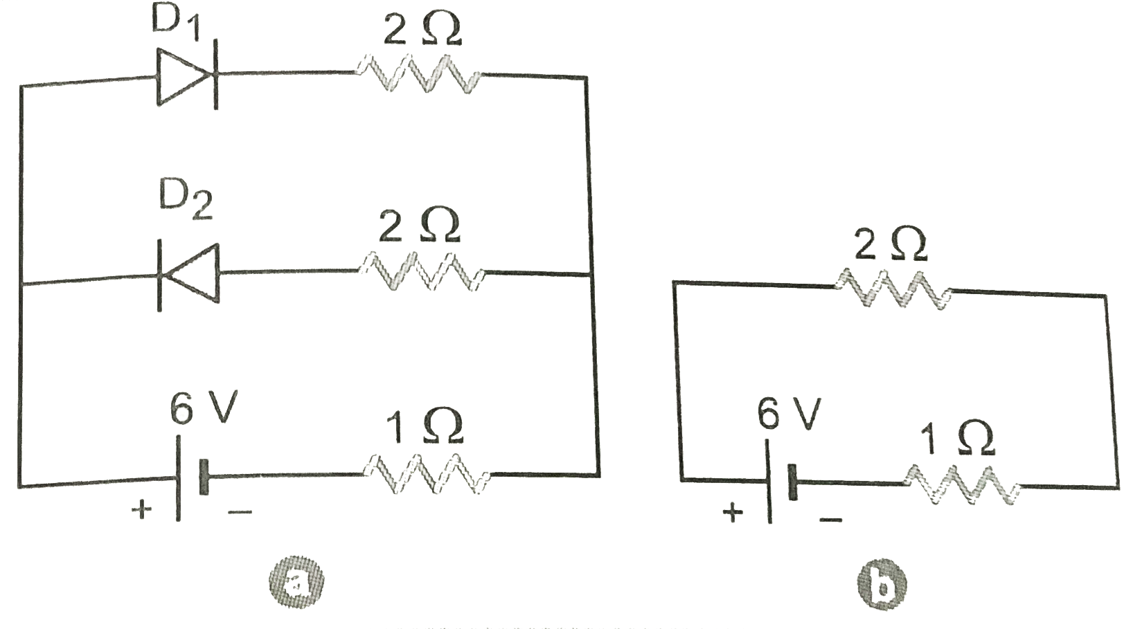
View SolutionFor the circuit shown in Fig., find the current flowing through the 1Ω resistor. Assume that the two diode are ideal diode.
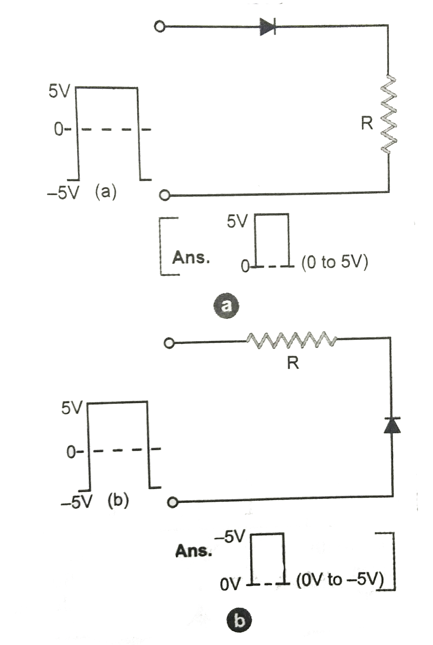
View SolutionIn the following circuit, if the input wave form is as shown in the figure, what will be the wave form (i) across R in Fig. and (ii) across the diode in Fig. Assume that the diode is ideal.
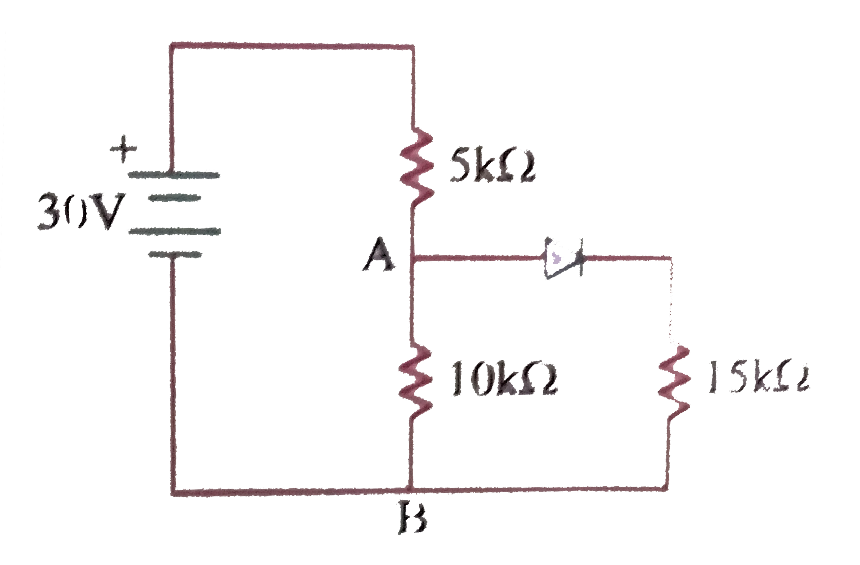
View SolutionFind the maximum voltage across AB in the circuit shown in Fig. Assume that diode is ideal.
 .
.
View SolutionIn the circuit shown. The potential drop across each capacitor is (assuming the two diodes are ideal). .
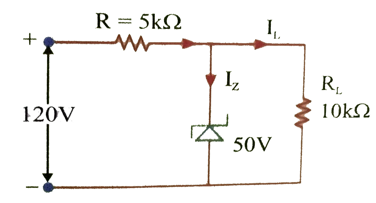
View SolutionFor the circuit shown in figure, Find
(1) the output voltage ,
(2) the voltage drop across series resistance ,
(3) the current through Zener diode.
 .
.
View SolutionAn ideal diode is connected in a circuit with resistance R=5Omega and V=10 volt as shown in figure maximum and minimum value of output voltage. When no load applied is (assume diode to be ideal)
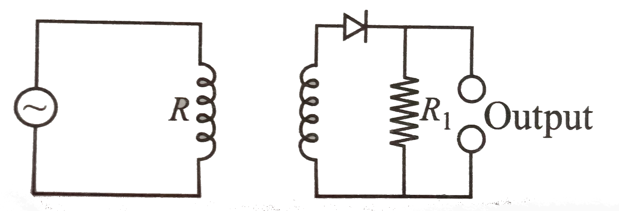
View SolutionA sinusoidal voltage of rms value 220 V is applied to a diode and a resistor R in the circuit shown in figure so that half wave rectification occurs. If the diode is ideal, what is the rms voltage across R1?
View SolutionIn the given circuit the voltage drop across the diode is 0.8 V, if the diode can withstand current upto maximum of 30 mA, then find the maximum voltage of the battery
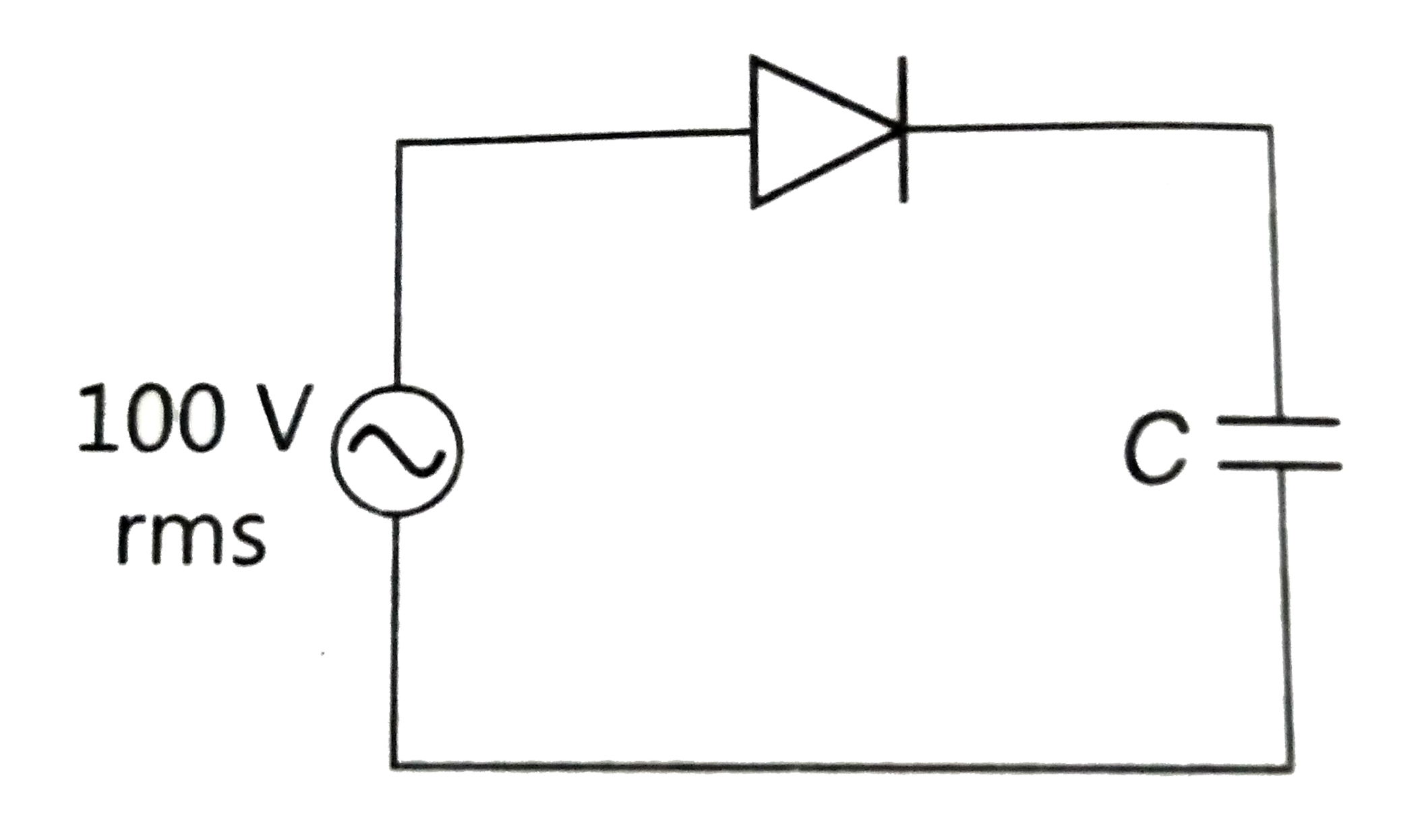
View SolutionA sinusoidal voltage of rms value 100V is connected to an ideal function diode as shown in figure. The final potential difference across the capacitor will be
View SolutionWhat is the voltage across an ideal p-n junction diode for shown circuit?

View Solution
