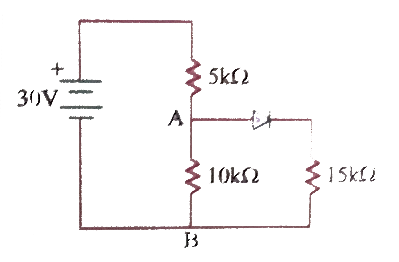
Find maximum voltage across AB in the circuit shown in Fig. Assume that diode is ideal.
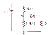
As the diode is treated ideal, its forward resistance Rf= zero.
It acts as short circuit. So, 10kΩ is in parallel with 15kΩ and the effective resistance across AB is
RAB=10×1510+15=10×1525=6kΩ
6kΩ in series with 5kΩ.
∴ total resistance =RT=6kΩ+5kΩ=11kΩ
V=30V Current drawn from the battery is
I=VRT=30V11kΩ=2.72mA
VAB=IRAB=2.72mA×6kΩ=16.32V
Topper's Solved these Questions
- SEMICONDUCTOR DEVICESBOOK - AAKASH SERIESCHAPTER - SEMICONDUCTOR DEVICESEXERCISE - EXERCISE - IA
13 Videos
- SEMICONDUCTOR DEVICESBOOK - AAKASH SERIESCHAPTER - SEMICONDUCTOR DEVICESEXERCISE - EXERCISE - II
31 Videos
- SEMICONDUCTOR DEVICESBOOK - AAKASH SERIESCHAPTER - SEMICONDUCTOR DEVICESEXERCISE - PRACTICE EXERCISE (LOGIC GATES )
5 Videos
- RAY OPTICSBOOK - AAKASH SERIESCHAPTER - RAY OPTICSEXERCISE - PROBLEMS ( LEVEL-II)
50 Videos
- UNITS AND MEASUREMENTBOOK - AAKASH SERIESCHAPTER - UNITS AND MEASUREMENTEXERCISE - PRACTICE EXERCISE
45 Videos
Similar Questions
Knowledge Check
In Fig.assuming the diode to be ideal
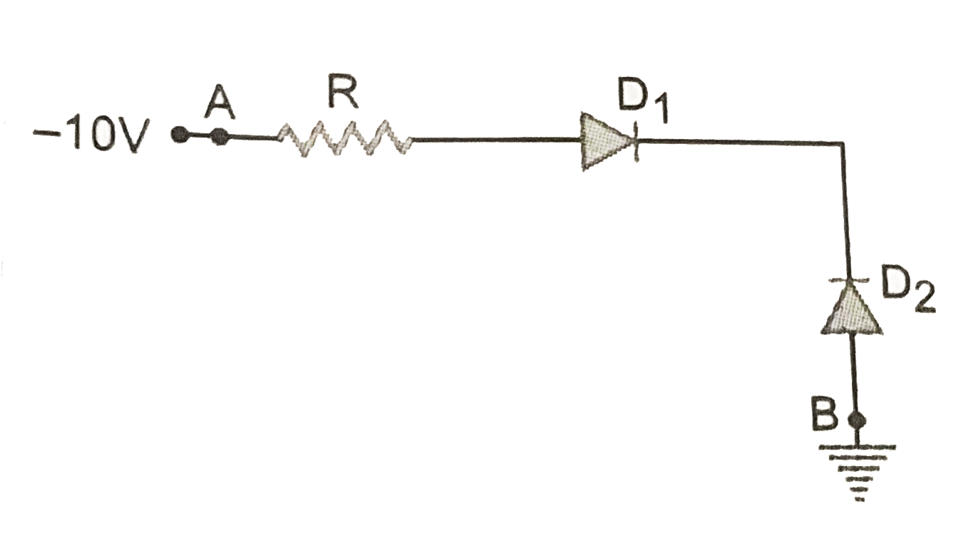 AD1 is forward biased and D2 is reverse biased and hence current flows from A to BBD2 is forward biased and D1 is reverse biased and hence no current flows from B to A and vice versaCD1 and D2 are both forward biased and hence current flows from A to BDD1 and D2 are both reverse biased and hence no current flows from A to B and vice versa
In Fig assuming the diodes to be ideal :
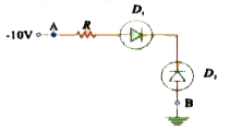 AD1 is forward biased and D2 is reverse biased and hence current flow form A to BBD2 is forward biased and D1 is reverse biased and hence no current flows from B to A and vice versaCD1andD2 are both forward biased and hence current flows from A to BDD1andD2 are both reverse biased and hence no current flows from A to B and vice-versa
In the circuit shown, the reading of the ammeter if diode is not ideal, will be
 A0B15mAC>15mAD<15mA
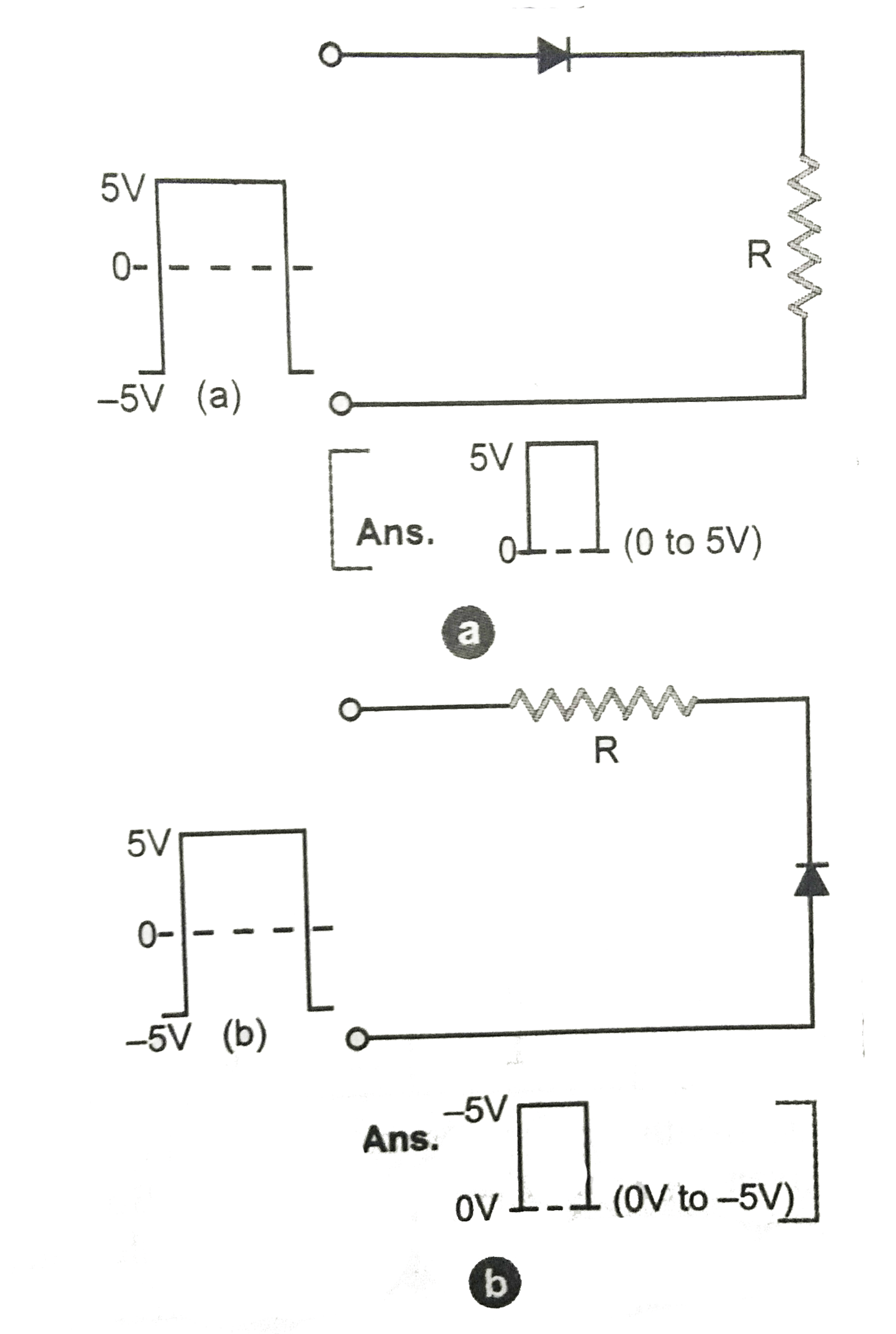
In the following circuit, if the input wave form is as shown in the figure, what will be the wave form (i) across R in Fig. and (ii) across the diode in Fig. Assume that the diode is ideal.
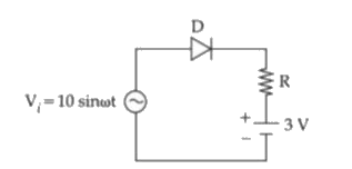
View SolutionChoose the correct waveform that can represent the voltage across R of the following circuit, assuming the diode is ideal one :
View Solution" Find the equivalent capacitance across AB for the circuit shown in fig.Every capacitor is having same capacitance "
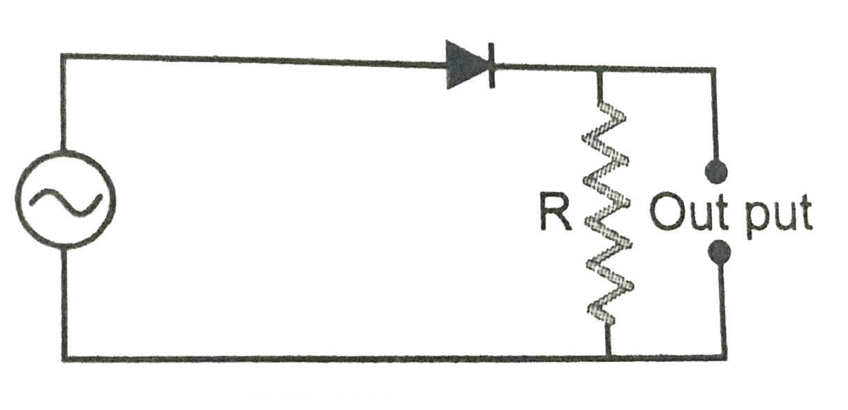
View SolutionA sinusoidal voltage of rms value 200 volt is connected to a diode and a resistor R in the circuit as shown in Fig., so that half wave rectification occurs. If the diode is ideal, what is the rms voltage across R? If resistor R is replaced by capactior of capacitance C, find the potential difference across C.
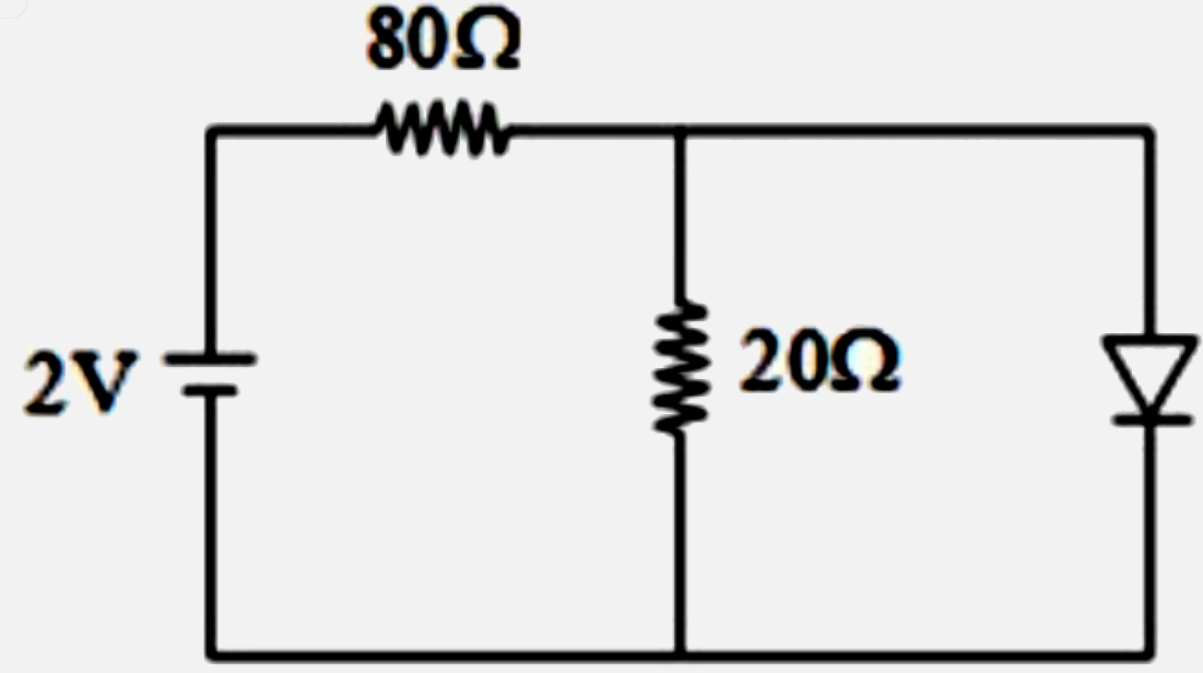
View SolutionIn the circuit shown, the current through the ideal diode is
View Solution

 .
.