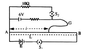
In the arrangement shown in the figure when the switch S2 is open, the galvanometer shows no deflection for l=L2. When the switchS2 is closed, the alvanometer shows no deflection for l=512L. The internal esistance of 6V cell, and the emf E of the other battery are respectively internal resistance of cell of emf E is negligible)
3Ω,8V
2Ω,12V
2Ω,24V
3Ω,12V
The correct Answer is:B
Topper's Solved these Questions
- APPENDICES ( REVISION EXERCISE )BOOK - AAKASH SERIESCHAPTER - APPENDICES ( REVISION EXERCISE )EXERCISE - REVISION EXERCISE (MOVING CHANGES & MEGNETISM)
95 Videos
- APPENDICES ( REVISION EXERCISE )BOOK - AAKASH SERIESCHAPTER - APPENDICES ( REVISION EXERCISE )EXERCISE - REVISION EXERCISE (ELECTRIC POTENTIAL & CAPACITANCE )
143 Videos
- ALTERNATING CURRENTBOOK - AAKASH SERIESCHAPTER - ALTERNATING CURRENTEXERCISE - EXERCISE - III
39 Videos
- APPENDICES (REVISION EXERCISE)BOOK - AAKASH SERIESCHAPTER - APPENDICES (REVISION EXERCISE)EXERCISE - LAW OF MOTION
91 Videos
Similar Questions
In the arrangement shown in figure when the switch S2 is open, the galvanometer shown no deflection for l=L/2. When the switch S2 is closed, the galvanometer shown no deflection for l=5L/12. The internal resistance (r) of 6V cell, and the emf E of the other battery are respectively

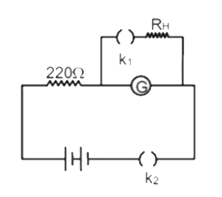
View SolutionAs shown in the figure initially switch k1 is open and k2 is closed and deflection of galvanometer is x. Now both switch are closed then the deflection in galvanometer is x/5 (given RH=5Ω). The resistance of galvanometer is
View Solution
Knowledge Check
In the arrangement shown in figure when the switch S2 is open, the galvanometer shown no deflection for l=L/2. When the switch S2 is closed, the galvanometer shown no deflection for l=5L/12. The internal resistance (r) of 6V cell, and the emf E of the other battery are respectively
 A3Ω,8VB2Ω,12VC2Ω,24VD3Ω,12V
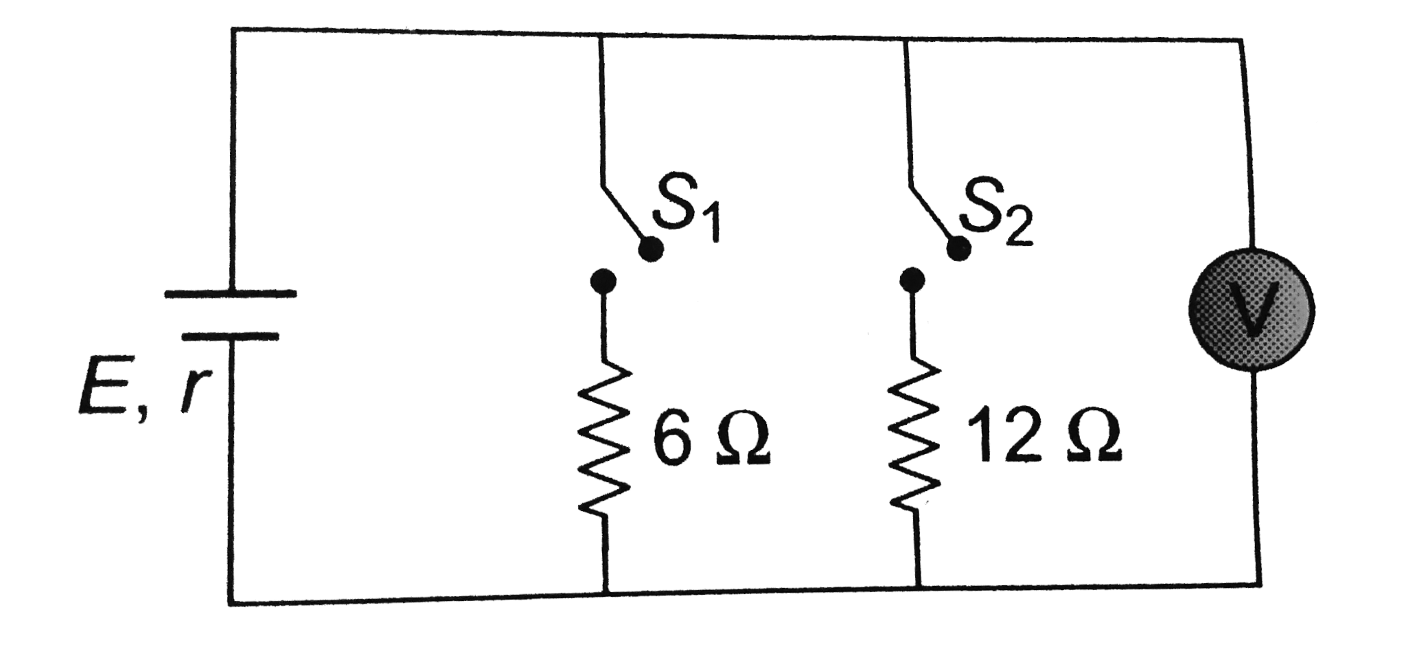
In the circuit shown, when switch S1 is closed and S2 is open, the ideal voltmeter shows a reaiding of 18V. When switch S2 is closed and S1 is open, the reading of voltmeter is 24V. When S1 and S2 both are closed, the voltmeter reading will be
 A14.4VB20.6VC24.4VD10.8V
In the potentiometer circuit shown in the figure the internal resistance of the 6V battery is 1Ω and length of the wire AB is 100 cm . When AD = 60 cm , the galvanometer shows no deflection . The EMF of the cell C is (the resistance of the wire AB is 2Ω )
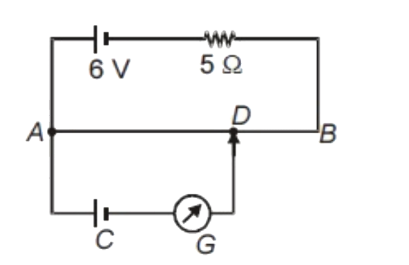
View SolutionIn the potentiometer circuit shown in the figure the internal resistance of the 6V battery is 1Ω and length of the wire AB is 100 cm . When AD = 60 cm , the galvanometer shows no deflection . The EMF of the cell C is (the resistance of the wire AB is 2Ω )

View SolutionIn the circuit shown, when switch S1 is closed and S2 is open, the ideal voltmeter shows a reaiding of 18V. When switch S2 is closed and S1 is open, the reading of voltmeter is 24V. When S1 and S2 both are closed, the voltmeter reading will be

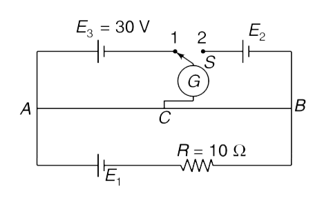
View SolutionIn the circuit shown in figure AB is a uniform wire of length L=5m. It has a resistance of 2Ω/m. When AC=2.0m, it was found that the galvanometer shows zero reading when switch s is placed in either of the two positions 1 or 2. find the emf E1.
View SolutionThree capacitors of capacitance C1=3μf,C2=6μfandC3=10μf, are connected to a 10V battery as shown in Figure 3 below
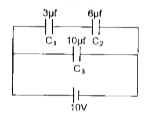
Calculate:
Equivalent capacitance
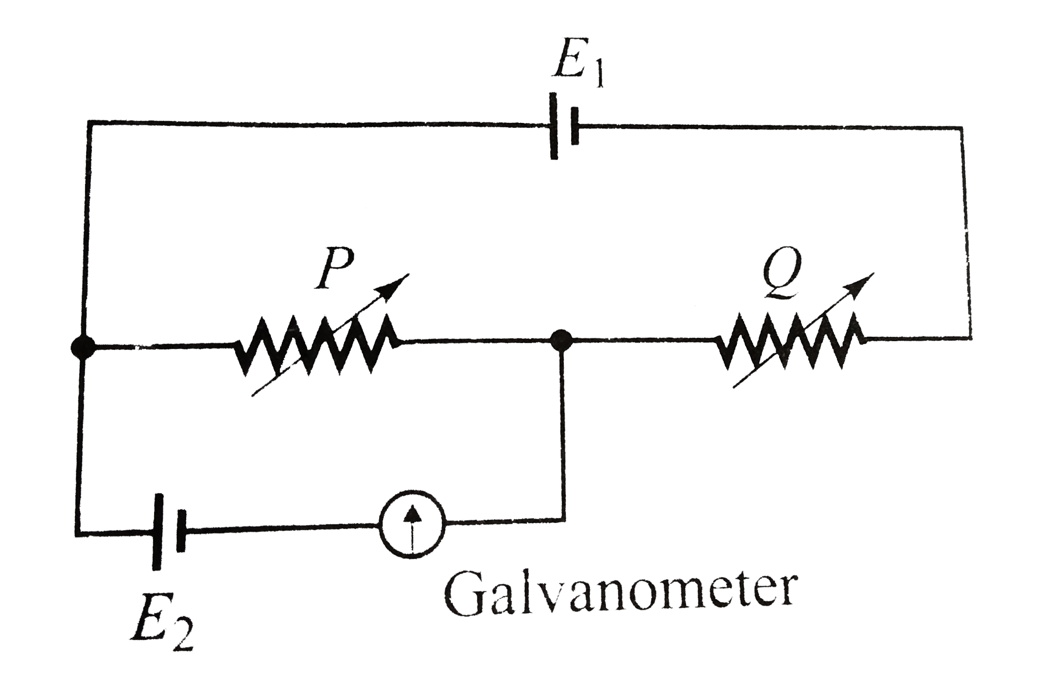
View SolutionTwo cells of emfs E1 and E2 and of negligible internal resistances are connected with two variable resistors as shown in Fig. A2.4. When the galvanometer shows no deflection, the values of the resistances are P and Q. What is the value of the ratio E2E1?
View Solution
