In the arrangement shown in figure when the switch S2 is open, the galvanometer shown no deflection for l=L/2. When the switch S2 is closed, the galvanometer shown no deflection for l=5L/12. The internal resistance (r) of 6V cell, and the emf E of the other battery are respectively

3Ω,8V
2Ω,12V
2Ω,24V
3Ω,12V
The correct Answer is:B
b. When switch S1 is open
6E=L2/L=12
∴E=12V
When switch S2 is closed, we get
6×10¹⁰+r=5L12LE=512×12=5
∴10+r=12orr=2Ω
Similar Questions
In the arrangement shown in, When the switch S is closed, find
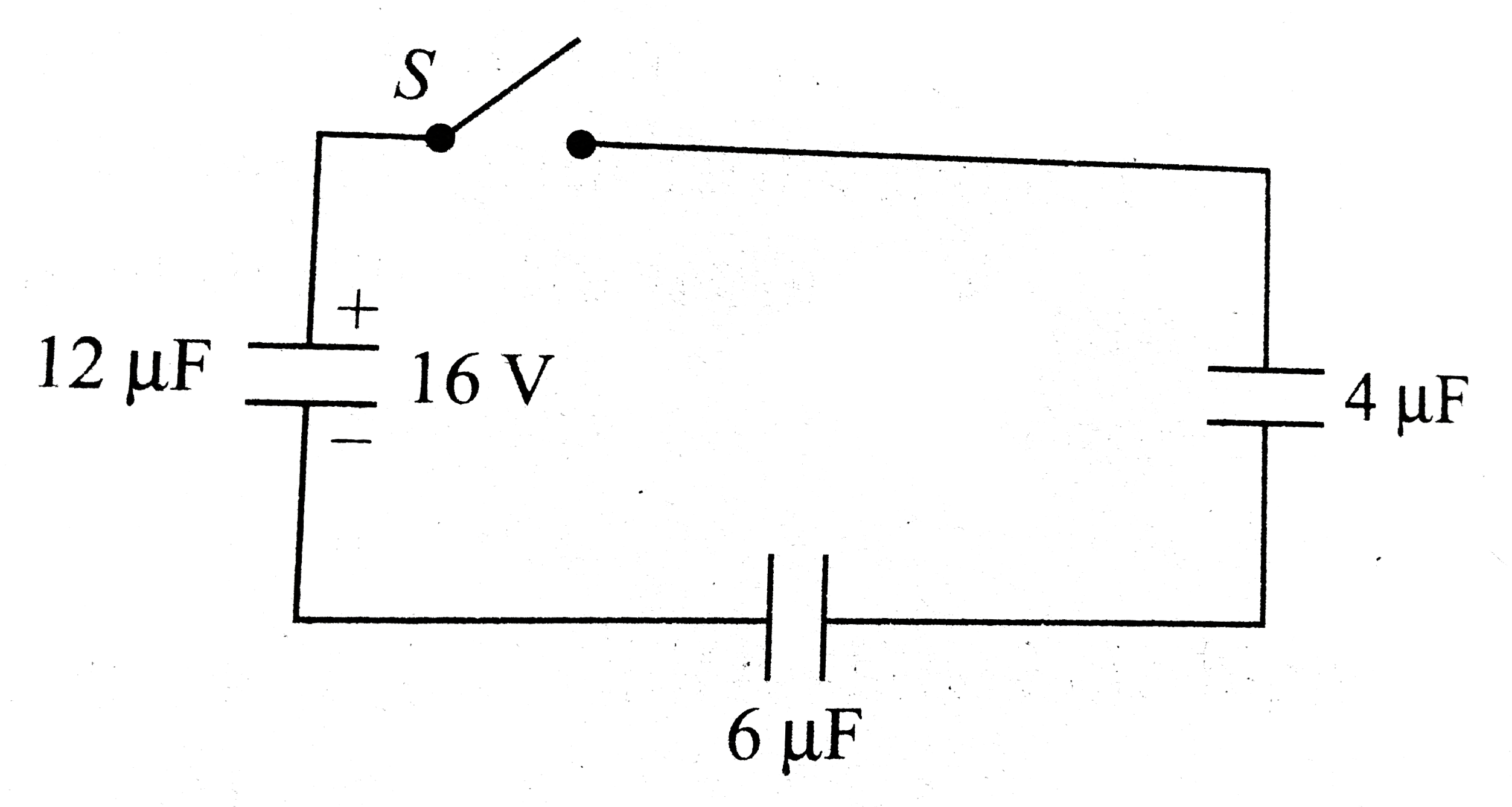 .
.
the final potential difference across the 12μF capacitor.View SolutionIn the circuits shown in the figures, the galvanometers show no deflection. Find the ratio of R1 and R2.
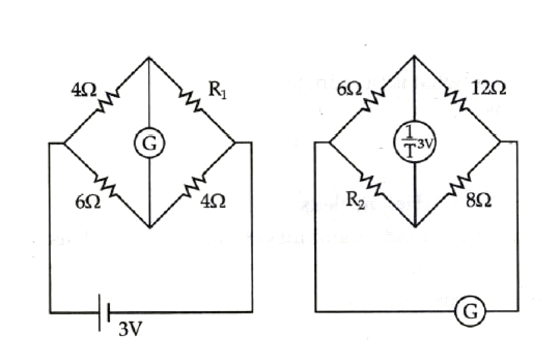 View Solution
Consider the situation shown in figure. The switch S is open for a long time and then closed.

Find the charge flown through the battery when the switch S is closed.View SolutionAs shown in the figure initially switch k1 is open and k2 is closed and deflection of galvanometer is x. Now both switch are closed then the deflection in galvanometer is x/5 (given RH=5Ω). The resistance of galvanometer is
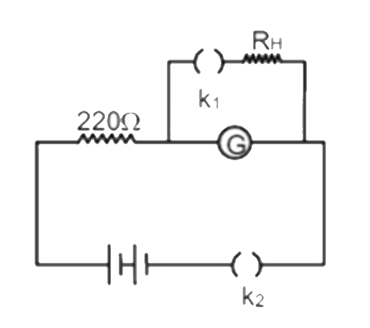 View Solution
Consider the situation shown in figure. The switch S is open for a long time and then closed.

Find the work done by the battery .View SolutionIn the potentiometer circuit shown in the figure the internal resistance of the 6V battery is 1Ω and length of the wire AB is 100 cm . When AD = 60 cm , the galvanometer shows no deflection . The EMF of the cell C is (the resistance of the wire AB is 2Ω )
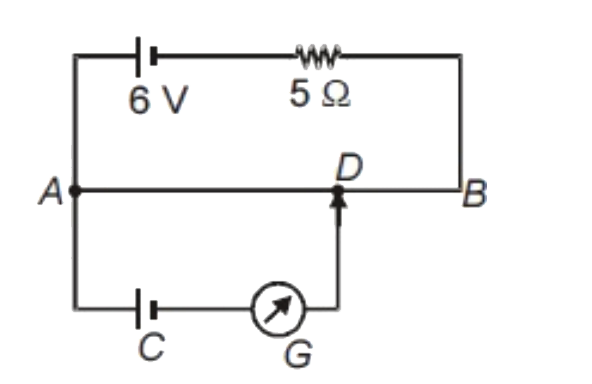 View Solution
A meter bridge setup is shown in the figure. If there is null deflection in galvanometer when length AC = 20 cm, then the value of resistance R is
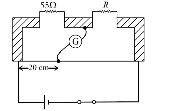 View Solution
In the potentiometer circuit shown in the figure the balance length AJ=60cm when switch S is open. When switch S is closed and the value of R=5Ω, the b alance length AJ=50cm. The internal resistance of the cell C' is
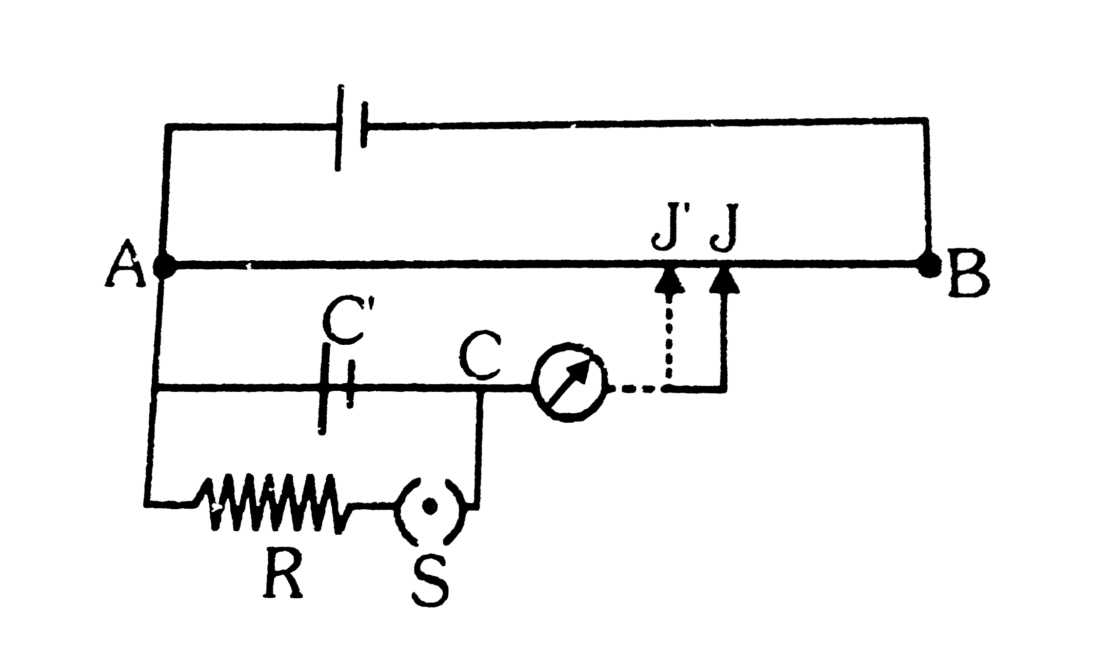 View Solution
On closing the switch S in the circuit as shown in the figure, the reading of the galvanometer G
 View Solution
A circuit consists of three identical lamps connected to a battery as shown in the figure. When the switch S is closed then the intensities of lamps A and B
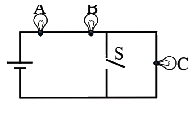 View Solution

