Derive an expression for the impedance of a series LCR circuit connected to an a.c. supply of variable frequency. Plot a graph showing variation of current with the frequency of the applied voltage. Explain briefly how the phenomenon of resonance in the circuit can be used in the tuning mechanism of a radio or TV set.
Graph showing variation of current with frequency of the applied voltage is shown in Fig. 7.44. Phenomenon of resonance plays an important role in the tuning mechanism of a radio or a TV set. The antenna of a radio accepts signals from various broadcasting stations. The signals picked up in the antenna acts as a source in the tuning circuit of the radio and so the circuit can be driven at many frequencies. However, to hear one particular radio station at one time we tune the radio. In tuning we vary the capacitance of a capacitor in the tuning circuit so that the resonant frequency of the circuit becomes almost equal to the frequency of the radio signal of a particular station. When this happens, the amplitude of the current with the frequency of the signal of particular radio station in the circuit is maximum and that programme is clearly Fig. 7.44 received.

Topper's Solved these Questions
- ALTERNATING CURRENT BOOK - U-LIKE SERIESCHAPTER - ALTERNATING CURRENT EXERCISE - SELF ASSESSMENT TEST (SECTION -A) (MULTIPLE CHOICE QUESTIONS)
4 Videos
- ALTERNATING CURRENT BOOK - U-LIKE SERIESCHAPTER - ALTERNATING CURRENT EXERCISE - SELF ASSESSMENT TEST (SECTION -A) (FILL IN THE BLANKS)
3 Videos
- ALTERNATING CURRENT BOOK - U-LIKE SERIESCHAPTER - ALTERNATING CURRENT EXERCISE - LONG ANSWER QUESTIONS -I
26 Videos
- ATOMSBOOK - U-LIKE SERIESCHAPTER - ATOMSEXERCISE - SELF ASSESSMENT TEST (SECTION C)
2 Videos
Similar Questions
Calculate the frequency of series resonance circuit. Define Q factor of this circuit. Explain briefly how the phenomenon of resonance in the circuit can be used in the tuning mechanism of a radio or TV set.
View SolutionSketch a graph showing the variation of impedance of LCR circuit the frequency of applied voltage.
View Solution
Knowledge Check
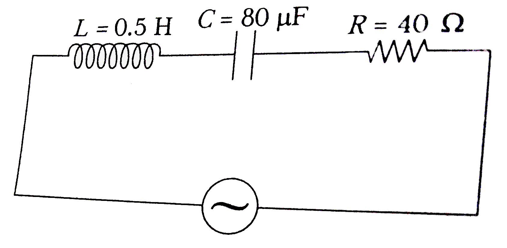
In the given figure , a series L-C-R circuit is connected to a variable frequency source of 230 V . The impedance and amplitude of the current at the resonating frequency will be
 A20Ω and 4.2 AB30Ω and 6.9 AC25Ω and 5.8 AD40Ω and 5.75 A
Figure shows a series LCR circuit connected to a variable frequency 230 V source.

The source frequency which drives the circuit the circuit in resonance isA4 HzB5 HzC6 HzD8 HzFigure shows a series LCR circuit connected to a variable frequency 230 V source.

The source frequency which drives the circuit the circuit in resonance isA4 HzB5 HzC6 HzD8 Hz
Mention the factors on which the resonant frequency of a series LCR circuit depends. Plot a graph showing variation of impedance of a series LCR circuit with the frequency of the applied a.c. source.
View SolutionIn the given figure , a series L-C-R circuit is connected to a variable frequency source of 230 V . The impedance and amplitude of the current at the resonating frequency will be

View SolutionDraw a labelled graph showing variation of impedance of a series LCR circuit with frequency of the a.c. supply.
View Solution(a) In a series LCR circuit connected across an a.c. source of variable frequency, obtain the expression for its impedance and draw a plot showing its variation with frequency of the a.c. source.
(b) What is the phase difference between the voltages across inductor and the capacitor at resonance in the LCR circuit ?
(c) When an inductor is connected to a 200 V d.c. voltage, a current of 1 A flows through it. When the same inductor is connected to a 200 V, 50 Hz a.c. source, only 0.5 A current flows. Explain, why ? Also, calculate the self inductance of the inductor.
View SolutionSeries LCR circuit is connected to an AC source of angular frequency ω. Current flowing in the circuit is found to lead the voltage by π/4. Magnitude of capacitance is
View Solution
