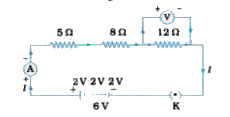
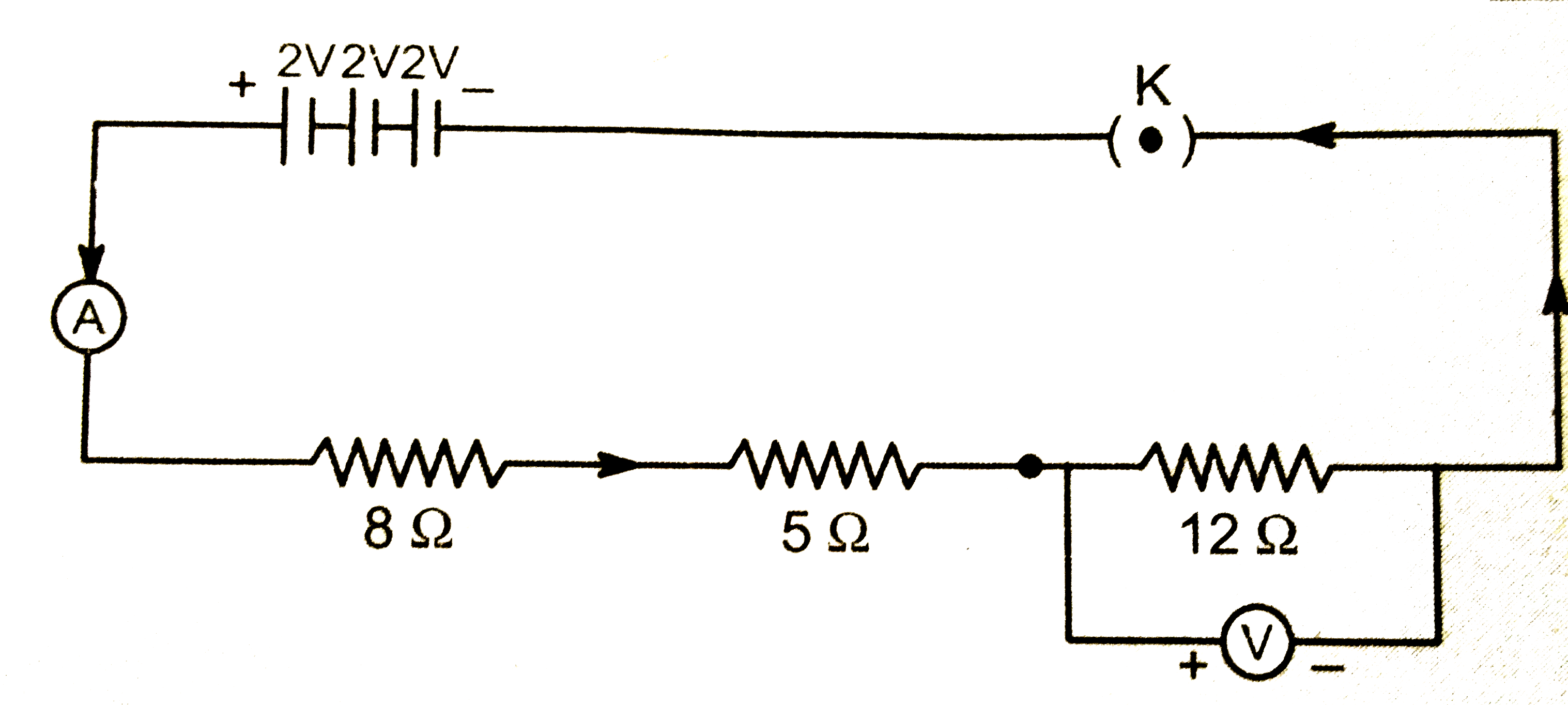
Redraw the circuit of 9.39, putting in an ammeter to measure the current through the resistors and a voltmeter to measure the potential difference across the 12Ω resistor. What would be the readings in the ammeter and the voltmeter ?Solution in Gujrati
The circuit diagram of above with an ammeter A and a voltmeter Vacross 12Ω resistor is shown in figure

Calculation of current flowing in the circuit :
Equivalent resistance of the circuit,
Rs=5Ω+8Ω+12Ω=25Ω
In a series combination, the current flowing through each resistor is the same and equal to the total current flowing through the circuit.
∴ Current through the resistors,
I+VR
=625
=0.24A
Since the current in the circuit and the current through each resistor is the same, the ammeter will show a reading of 0.24 A.
Calculation of potential difference across 122 resistor :
As total current 0.24 A flows in the circuit, the same current 0.24 A would also flow through the 122 resistor which is connected in series.
∴ The potential difference across the 12 12 resistor,
V=IR
=0.24×12=2.88V
Thus, the p.d. across 12Ω resistor is 2.88 volt.
So, the voltmeter will show a reading of 2.88 V.
Topper's Solved these Questions
- BOOK - KUMAR PRAKASHANCHAPTER - ELECTRICITYEXERCISE - QUESTIONS AND ANSWERS (TEXTBOOK ILLUSTRATIONS)14videos
ELECTRICITY
- BOOK - KUMAR PRAKASHANCHAPTER - ELECTRICITYEXERCISE - QUESTIONS AND ANSWERS (MORE TO KNOW)1videos
ELECTRICITY
- BOOK - KUMAR PRAKASHANCHAPTER - ELECTRICITYEXERCISE - PRACTICAL SKILL BASED QUESTION WITH ANSWERS20videos
ELECTRICITY
- BOOK - KUMAR PRAKASHANCHAPTER - MAGNETIC EFFECTS OF ELECTRIC CURRENT EXERCISE - VALUE BASED QUESTIONS WITH ANSWERS15videos
MAGNETIC EFFECTS OF ELECTRIC CURRENT
Similar Questions
A current of 0.5 A is drawn by a filament of an electric bulb for 10 minutes. Find the amount of eletric charge that flows through the circuit.
05:06View SolutionHow does a metal conduct electricity ?
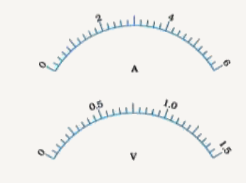
03:22View SolutionThe scales of an ammeter and a voltmeter are shown below:

What is the range of the ammeter and the range of the voltmeter?View SolutionShalini and his brother Amey observed a water-pump working , Shalini inquired how an electric motor works . Amey collected different parts of an electric motor e.g., field - magnets , cabon- brushes , armature , battery , switch, connecting wire , split - rings , etc, and showed them to Shalini . Amey then explained how an armature could rotate.
State the principle how an electric motor to works .10:09View SolutionRedraw the circuit of Q.12, putting in an ammeter to measure the current through the resistors and a voltmeter to measure the voltage across the 12ohm resistor. What would be the readings in the ammeter and the voltmeter ?
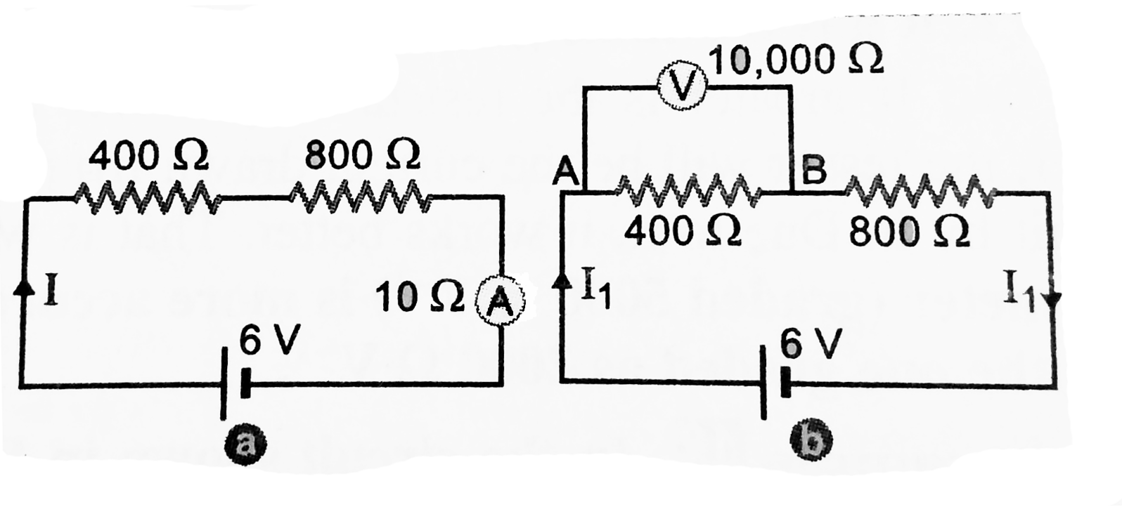
10:07View SolutionTwo resistors 400Omega and 800Omega are connected in series with a 6V battery. It is desired to measure the current in the circuit. An ammeter of 10Omega resistance is used for this purpose figure. What will be the reading in the ammeter? Similarly, if a voltmeter of 10,000Omega resistance is used to measure the potential difference across the 400Omega resistor, what will be the reading in the voltmeter?
03:22View SolutionTo study the dependence of current (I) on the potential difference (V) across a resistor, the correct way of connecting the ammeter and voltmeter in the circuit is :
06:06View Solution400 ओम तथा 800 ओम के दो प्रतिरोध 6 वोल्ट की बैटरी के साथ श्रेणीक्रम में जुड़े है । परिपथ में धारा नापने के लिये 10 ओम प्रतिरोध का एक अमीटर प्रयुक्त किया गया । अमीटर का पाठ्यांक क्या होगा ? इसी प्रकार , यदि 400 ओम प्रतिरोधक के सिरों के बीच विभवांतर नापने के लिये 10,000 ओम का वोल्टमीटर प्रयुक्त किया जाये , तो वोल्टमीटर में पाठ्यांक क्या होगा ?
01:30View Solutionप्रश्न 1 का परिपथ दोषारा खींचिए तथा इसमें प्रतिरोधकों से प्रवाहित विद्युत धारा को मापने के लिए मीटर तथा 12Ω के प्रतिरोधक के सिरों के बीच विभवांतर मापने के लिए वोल्टमीटर लगाइए। एमीटर तथा वोल्टमीटर के क्या पाठ्यांक होंगे?
 View Solution
Two resistors 400Ω and 800Ω are connected in series with a 6V battery. It is desired to measure the current in the circuit. An ammeter of 10Ω resistance is used for this purpose figure. What will be the reading in the ammeter? Similarly, if a voltmeter of 10,000Ω resistance is used to measure the potential difference across the 400Ω resistor, what will be the reading in the voltmeter?
 02:06View Solution
Redraw the circuit of question 1, putting in an ammeter to measure the current through the resistors and a voltmeter to measure potential difference across the 12 Ω resistor. What would be the readings in the ammeter and the voltmeter?
View SolutionWhich circuit diagram shows voltmeter V and ammeter A correctly positioned to measure the total potential difference of the circuit and the current through each resistor?
03:23View SolutionRedraw the circuit of Question 1, putting in an ammeter to measure to current through the resistors and a voltmeter to measure the potential difference across the 12Ω resistor. What would be the readings in the ammeter and the voltmeter?
02:27View SolutionRedraw the circuit of Q.12, putting in an ammeter to measure the current through the resistors and a voltmeter to measure the voltage across the 12ohm resistor. What would be the readings in the ammeter and the voltmeter ?
02:16View SolutionWhich circuit diagram shows voltmeter V and ammeter A correctly positioned to measure the total potential difference of the circuit and the current through each resistor?
View Solution

