Obtain the resonance angular frequency for the circuit shown in figure.

Here inductor L and resistance R are in series. If Z1 is its resultant impedance then
Z1=R+jXL=R+jωL
This Z1 and capacitor C are in parallel . So the resultant impedance Z for about circuit.
1Z=1R+jωL+jωC ⎡⎣∴1−1ωCj=−ωCj=jωC⎤⎦
=R−jωLR2+ω2L2+jωC
[ Multiplying and dividing the first term on the right hand side by R=jωL]
=R+j(ωCR2+ω2L2C−ωL)R2+ω2L2
∴Z=R2+ω2L2R+j(ωCR2+ω2L2C−ω)
The imaginary part (coefficient of j ) in the denominator of the above equation should be zero, for Z to be maximum.
∴ωCR2+ω3L2C−ωL=0
∴ω2L2C=L−CR2
∴ω2=1LC−R2L2
∴ω=√1LC−R2L2
Topper's Solved these Questions
- BOOK - KUMAR PRAKASHANCHAPTER - ALTERNATING CURRENTS EXERCISE - SECTION-C NCERT EXEMPLAR (MCQs)7videos
ALTERNATING CURRENTS
- BOOK - KUMAR PRAKASHANCHAPTER - ALTERNATING CURRENTS EXERCISE - SECTION-C NCERT EXEMPLAR (More than one Options)6videos
ALTERNATING CURRENTS
- BOOK - KUMAR PRAKASHANCHAPTER - ALTERNATING CURRENTS EXERCISE - SECTION B NUMERICALS (ADDITONAL EXERCISE )32videos
ALTERNATING CURRENTS
- BOOK - KUMAR PRAKASHANCHAPTER - ATOMSEXERCISE - Section-D -MCQs asked in GUJCET / Board Exam34videos
ATOMS
Similar Questions
Knowledge Check
- Question 1 - Select One
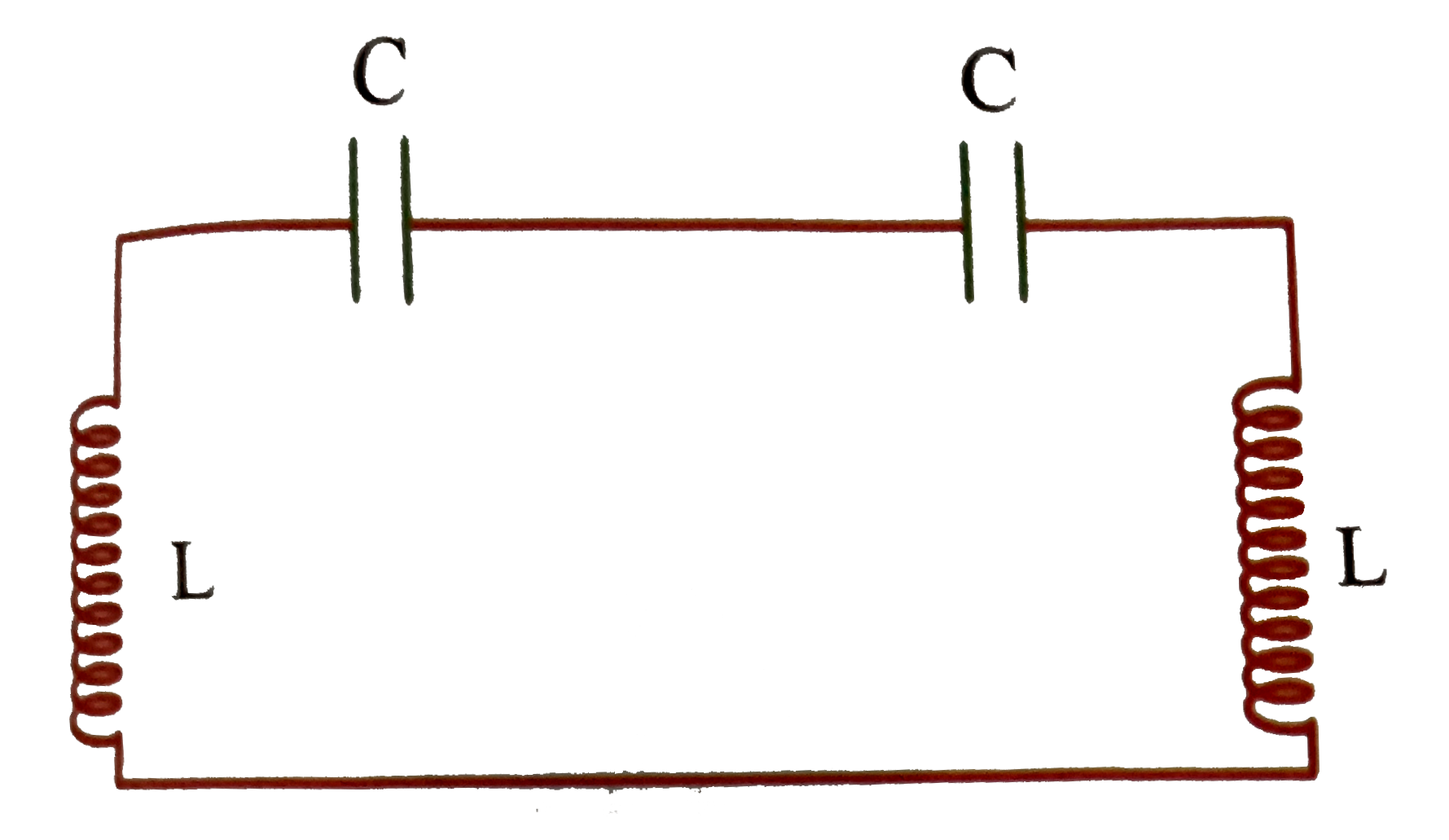
The natural frequency of the circuit shown in the figure is
 A12π√LCB1π√LCC2π√LCDnone
 - Question 2 - Select One
The resonant frequency of an L - C circuit is
A12π√LCB12π√LCC12π√LCD12π√CL - Question 3 - Select One
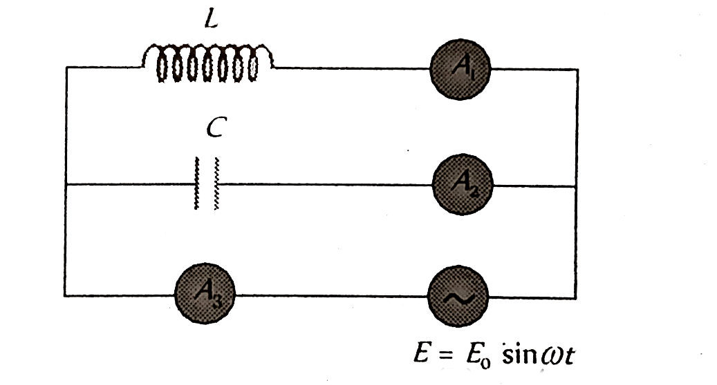
An inductor L and a capacitor C are connected in the circuit as shown in the figure. The frequency of the power supply is equal to the resonant frequency of the circuit. Which ammeter will read zero ampere
 AA1BA2CA3DNone of these
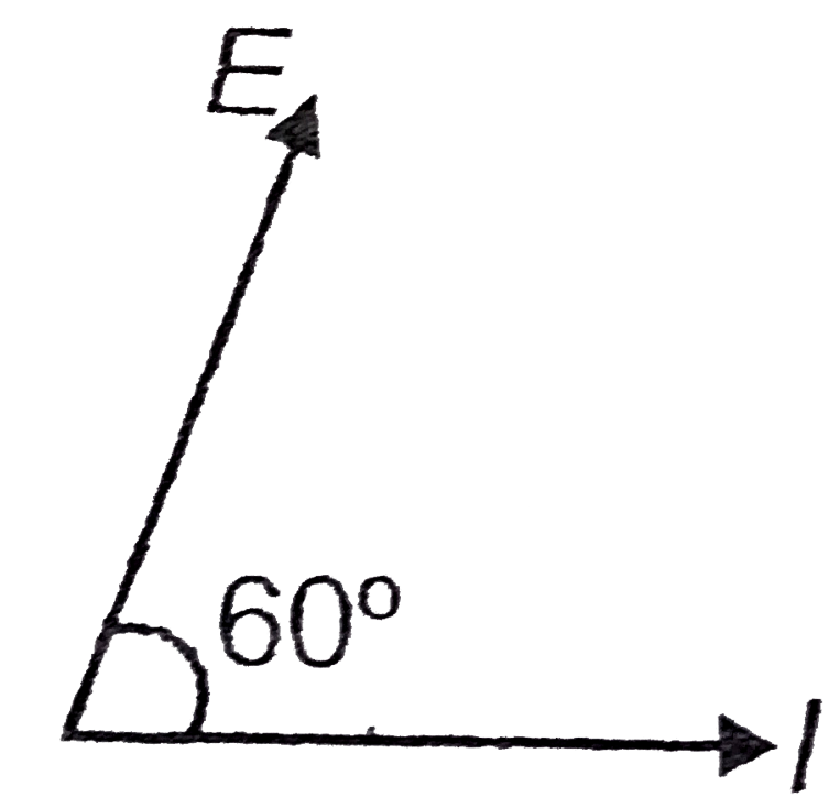
Phase relationship between current (l) and applied voltage (E) for a series LCR circuit is shown here. ω0 = Resonant angular frequency of the circuit and ω= Applied angular frequency .
 View Solution
Phase relationship between current (l) and applied voltage (E) for a series LCR circuit is shown here. ω0 = Resonant angular frequency of the circuit and ω= Applied angular frequency .
 View Solution
An inductor L and a capacitor C are connected in the circuit as shown in the figure. The frequency of the power supply is equal to the resonant frequency of the circuit. Which ammeter will read zero ampere
 View Solution
An inductor of 10mH an a capacitor of 16mF are connected in the circuit as shown in figure The frequency of the power supply is equal to the resonant frequency of the circuit Which ammeter will read will zero ampere
 .View Solution
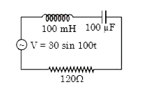
In a series L-C-R circuit shown in the figure , what is the resonance frequency and the current at the resonating frequency?
View Solution

