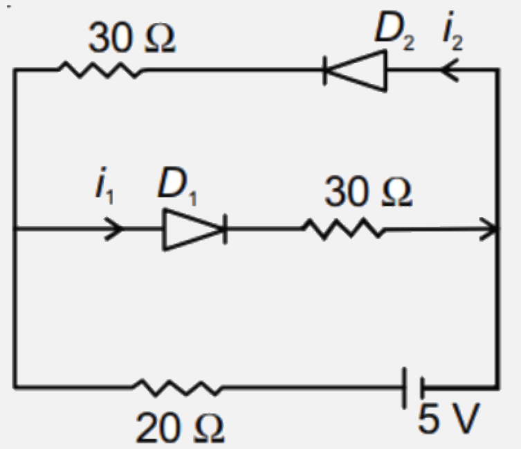
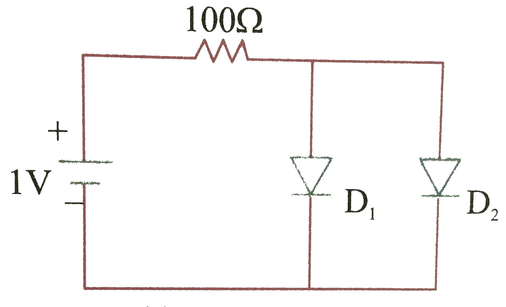
Considering the circuit and data given in the diagram, calculate the currents flowing in the diodes D1 and D2. Forward resis- tance of D1andD2 is 20Ω
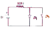
Since the positive terminal of battery is connected to P-type of both diodes D1andD2 they are forward biased. These diodes are replaced by with their forward resistances as shown in Fig.
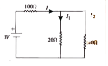
The resistance of 20Ω in parallel
1R=120+120=220
Therefore, total current I in the circuit
I=1100+10=1110 amp and
I1=I2=12×1110=1220 amp
Topper's Solved these Questions
- SEMICONDUCTOR DEVICESBOOK - AAKASH SERIESCHAPTER - SEMICONDUCTOR DEVICESEXERCISE - EXERCISE - IA
13 Videos
- SEMICONDUCTOR DEVICESBOOK - AAKASH SERIESCHAPTER - SEMICONDUCTOR DEVICESEXERCISE - EXERCISE - II
31 Videos
- SEMICONDUCTOR DEVICESBOOK - AAKASH SERIESCHAPTER - SEMICONDUCTOR DEVICESEXERCISE - PRACTICE EXERCISE (LOGIC GATES )
5 Videos
- RAY OPTICSBOOK - AAKASH SERIESCHAPTER - RAY OPTICSEXERCISE - PROBLEMS ( LEVEL-II)
50 Videos
- UNITS AND MEASUREMENTBOOK - AAKASH SERIESCHAPTER - UNITS AND MEASUREMENTEXERCISE - PRACTICE EXERCISE
45 Videos
Similar Questions
Knowledge Check
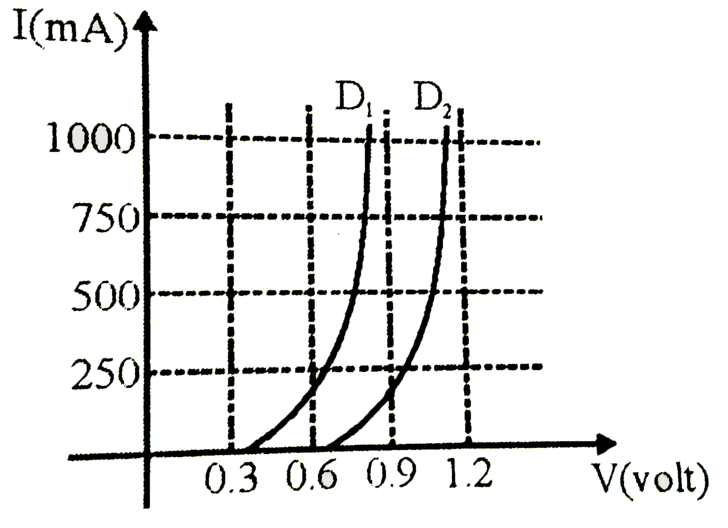
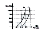
The forward bias characteristics of two diodes D1 and D2 are shown, the knee voltage for D1 and D2 respectively [approx]-A0.4 V and 0.7 VB0.6 V and 0.9 VC0.6 V and 0.8 VD0.4 V and 0.9 VIn the following circuit of PN junction diodes D1,D2 and D3 are ideal then i is
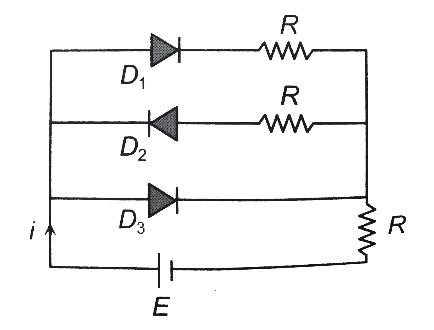 AE/RBE/2RC2E/3RDZero
The currents through diodes D1andD2 are
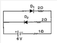
View SolutionAll the diodes are ideal. The current flowing in 2Ω resistor connected between the diodes D1 and D2 is
View SolutionThe ideal diodes D1 and D2 are to be connected in the positions shown in the circuit shown below
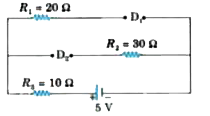
calculate the current in the circuit
(i) when p side of D1 is connected to resistance R1 and p side of D2 is connected to resistance R2
(ii) when n side of D1 connected to resistance R1 and n side of D2 is connected to resistance R2
View SolutionFor the circuit shown here, find the current flowing through the 1Ω resistor. Assume that the two diodes D1 and D2 are ideal diodes.
View SolutionIn the following circuit of PN junction diodes D1,D2 and D3 are ideal then i is

View SolutionThe forward bias characteristics of two diodes D1andD2 are shown, the knee voltage for D1andD2 are respectively (approx)
View Solution

 .
.