All the diodes are ideal. The current flowing in 2Ω resistor connected between the diodes D1 and D2 is
1A
2A
3A
Zero
The correct Answer is:A
To find the current flowing through the 2 Ω resistor connected between the diodes D1 and D2, we can follow these steps:
Step 1: Analyze the Circuit
First, we need to understand the configuration of the circuit. We have a voltage supply of 10 volts and several resistors and diodes. The resistors are connected in a combination of series and parallel configurations.
Step 2: Calculate the Total Resistance
Identify the resistors in series and parallel:
- The resistors in the upper part of the circuit are 1 Ω, 2 Ω, and 1 Ω in series.
- The total resistance of these resistors in series is:
Rupper=1Ω+2Ω+1Ω=4Ω
- The 4 Ω resistor and the 3 Ω resistor are in series with the upper part:
Rtotal=Rupper+3Ω=4Ω+3Ω=7Ω
Step 3: Identify Parallel Resistors
Now, we need to consider the 4 Ω resistor in parallel with another 4 Ω resistor:
- The equivalent resistance of two 4 Ω resistors in parallel is given by:
1Rparallel=14+14=24⟹Rparallel=2Ω
Step 4: Calculate the Total Resistance in the Circuit
Now, we can find the total resistance in the circuit:
- The total resistance now becomes:
Rtotal=7Ω+2Ω=9Ω
Step 5: Calculate the Total Current
Using Ohm's law (V = IR), we can find the total current flowing through the circuit:
I=VRtotal=10V9Ω≈1.11A
Step 6: Determine Current through the 2 Ω Resistor
Since the 2 Ω resistor is connected between D1 and D2, we need to analyze the current division:
- The current through the 2 Ω resistor will be half of the total current since it is in parallel with another resistor of equal value (assuming the other resistor is also 2 Ω):
I2Ω=I2=1.11A2≈0.56A
Final Answer
The current flowing through the 2 Ω resistor is approximately 0.56 A.
---
First, we need to understand the configuration of the circuit. We have a voltage supply of 10 volts and several resistors and diodes. The resistors are connected in a combination of series and parallel configurations.
Identify the resistors in series and parallel:
- The resistors in the upper part of the circuit are 1 Ω, 2 Ω, and 1 Ω in series.
- The total resistance of these resistors in series is:
Rupper=1Ω+2Ω+1Ω=4Ω
Rtotal=Rupper+3Ω=4Ω+3Ω=7Ω
Now, we need to consider the 4 Ω resistor in parallel with another 4 Ω resistor:
- The equivalent resistance of two 4 Ω resistors in parallel is given by:
1Rparallel=14+14=24⟹Rparallel=2Ω
Now, we can find the total resistance in the circuit:
- The total resistance now becomes:
Rtotal=7Ω+2Ω=9Ω
Using Ohm's law (V = IR), we can find the total current flowing through the circuit:
I=VRtotal=10V9Ω≈1.11A
Since the 2 Ω resistor is connected between D1 and D2, we need to analyze the current division:
- The current through the 2 Ω resistor will be half of the total current since it is in parallel with another resistor of equal value (assuming the other resistor is also 2 Ω):
I2Ω=I2=1.11A2≈0.56A
The current flowing through the 2 Ω resistor is approximately 0.56 A.
Topper's Solved these Questions
- SEMICONDUCTOR ELECTRONICS (MATERIAL, DEVICES AND SIMPLE CIRUITS )Book:AAKASH INSTITUTE ENGLISHChapter:SEMICONDUCTOR ELECTRONICS (MATERIAL, DEVICES AND SIMPLE CIRUITS )Exercise:Assignment section -C (Previous years type question)
Explore 110 Videos
- SEMICONDUCTOR ELECTRONICS (MATERIAL, DEVICES AND SIMPLE CIRUITS )Book:AAKASH INSTITUTE ENGLISHChapter:SEMICONDUCTOR ELECTRONICS (MATERIAL, DEVICES AND SIMPLE CIRUITS )Exercise:Assignment SECTION - D (Assertion & reason type Question)
Explore 10 Videos
- SEMICONDUCTOR ELECTRONICS (MATERIAL, DEVICES AND SIMPLE CIRUITS )Book:AAKASH INSTITUTE ENGLISHChapter:SEMICONDUCTOR ELECTRONICS (MATERIAL, DEVICES AND SIMPLE CIRUITS )Exercise:Assignment section -A (Objective Type Question)
Explore 43 Videos
- RAY OPTICS AND OPTICAL INSTRUMENTSBook:AAKASH INSTITUTE ENGLISHChapter:RAY OPTICS AND OPTICAL INSTRUMENTSExercise:ASSIGNMENT (SECTION - D)
Explore 16 Videos
- SEMICONDUCTOR ELECTRONICS: MATERIALS, DEVICES AND SIMPLE CIRCUITSBook:AAKASH INSTITUTE ENGLISHChapter:SEMICONDUCTOR ELECTRONICS: MATERIALS, DEVICES AND SIMPLE CIRCUITSExercise:Assignment (Section-D (Assertion and reason))
Explore 5 Videos
Similar Questions
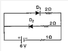
For the circuit shown here, find the current flowing through the 1Ω resistor. Assume that the two diodes D1 and D2 are ideal diodes.
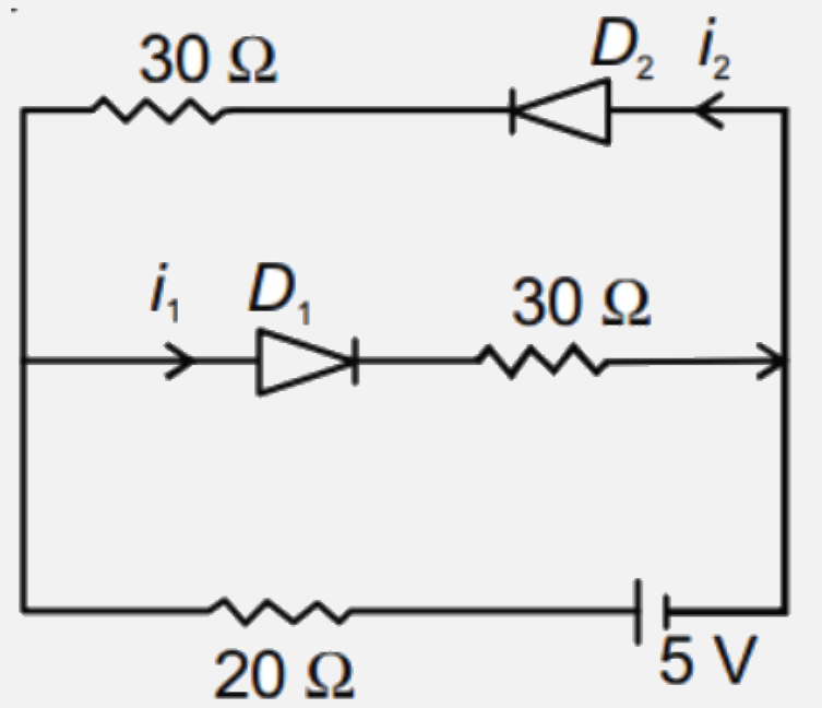
View SolutionThe currents through diodes D1andD2 are
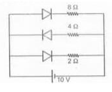
View SolutionThe current through 2 Omega resistor is(diodes are considered as ideal)
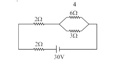
View SolutionThe current (in A) flowing through 6Ω resistor in the following circuit is:
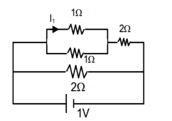
View SolutionThe current I1 (in A) flowing through the 1Ω resistor in the given circuit is
View SolutionAll resistance shown in the circuit are 2Ω each. The current in the resistance between D and E is
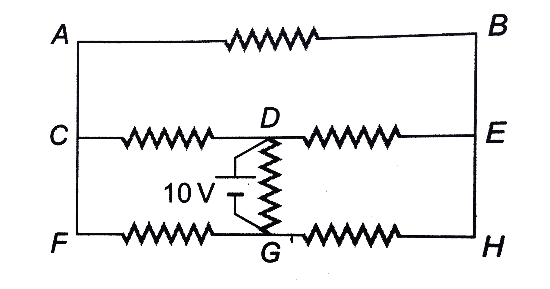
View SolutionAll resistance shown in the circuit are 2Ω each. The current in the resistance between D and E is

View SolutionIn the circuit of the figure, treat diode as ideal, current in the 4Ω resistor is
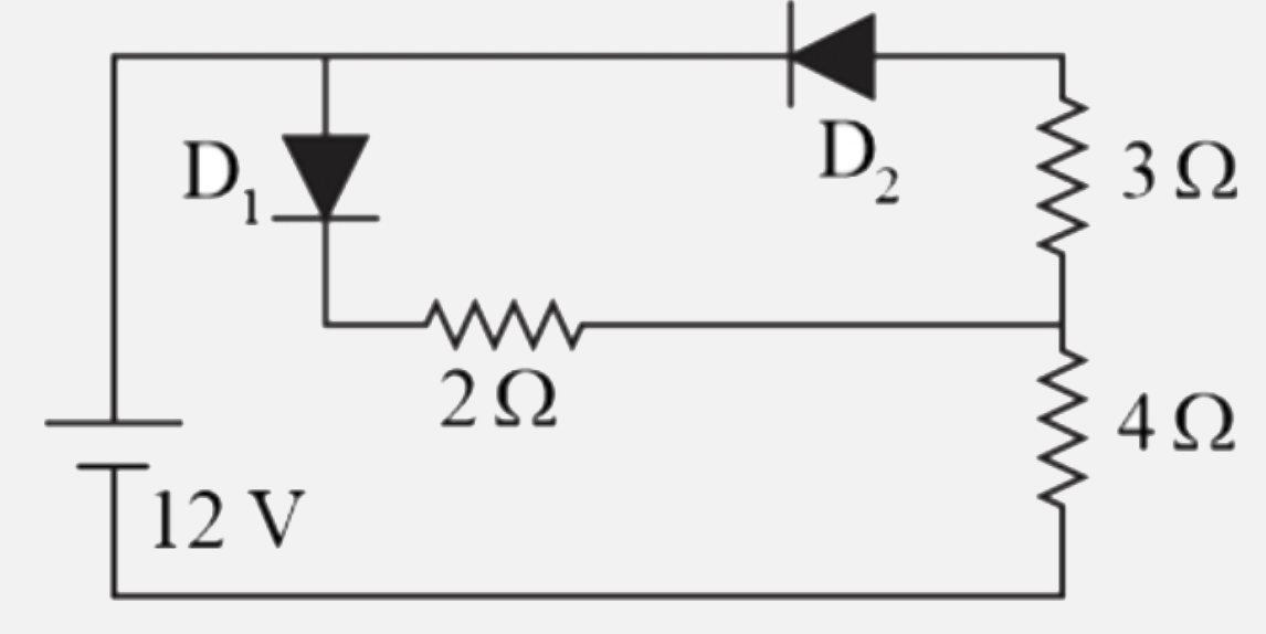
View SolutionThe current I1 ( in A ) flowing through 1 Ω resistor in the following circuit is :
View SolutionThe current I1 (in A) flowing through 3Ω resistor in the following circuit is:

View Solution
