Draw the circuit for experimental verification of Ohm's law using a source of variable DC voltage, a main resistance of 100Ω, two galvanometers and two resistances of value 106Ω and 10−3Ω respectively. Clearly show the positions of the voltmeter and the ammeter.
To draw the circuit for the experimental verification of Ohm's law using the specified components, follow these steps:
Step 1: Identify the Components
We need to include:
- A variable DC voltage source (E)
- A main resistance of 100 Ω (R)
- Two galvanometers (G1 and G2)
- Two resistances: 10^6 Ω (R1) and 10^-3 Ω (R2)
Step 2: Position the Voltage Source
Start by placing the variable DC voltage source (E) on the left side of the circuit diagram. This will be the source of power for the circuit.
Step 3: Connect the Main Resistance
Connect the main resistance (100 Ω) in series with the voltage source. This means that the current from the voltage source will first pass through this resistance.
Step 4: Connect the Ammeter
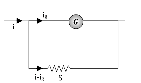
To measure the current flowing through the circuit, connect the first galvanometer (G1) in series with the main resistance. Since this galvanometer will act as an ammeter, we need to connect a shunt resistance (R2 = 10^-3 Ω) in parallel with it. This allows the majority of the current to bypass the galvanometer, protecting it from high currents.
Step 5: Connect the Voltmeter
Next, to measure the voltage across the main resistance, connect the second galvanometer (G2) in parallel with the main resistance. This galvanometer will act as a voltmeter. To do this, connect a high-value shunt resistance (R1 = 10^6 Ω) in series with G2. This ensures that the voltmeter measures the potential difference across the main resistance accurately.
Step 6: Complete the Circuit
Finally, connect the other terminal of the main resistance back to the negative terminal of the variable DC voltage source, completing the circuit.
Final Circuit Diagram
The final circuit diagram should look like this:
±−−(E)−−−(100Ω)−−−±−−(G1)−−−+||||±−−(R2)−−−+||||±−−(G2)−−−+|||±−−(R1)−−−−−−−−−−−+|||±−−−−−−−−−−−−−−−−−−−−−−−−−−−−−+
Summary of Connections:
- E: Variable DC voltage source
- 100 Ω: Main resistance in series
- G1: First galvanometer (ammeter) in series with shunt R2 (10^-3 Ω)
- G2: Second galvanometer (voltmeter) in parallel with main resistance and in series with shunt R1 (10^6 Ω)
We need to include:
- A variable DC voltage source (E)
- A main resistance of 100 Ω (R)
- Two galvanometers (G1 and G2)
- Two resistances: 10^6 Ω (R1) and 10^-3 Ω (R2)
Start by placing the variable DC voltage source (E) on the left side of the circuit diagram. This will be the source of power for the circuit.
Connect the main resistance (100 Ω) in series with the voltage source. This means that the current from the voltage source will first pass through this resistance.
To measure the current flowing through the circuit, connect the first galvanometer (G1) in series with the main resistance. Since this galvanometer will act as an ammeter, we need to connect a shunt resistance (R2 = 10^-3 Ω) in parallel with it. This allows the majority of the current to bypass the galvanometer, protecting it from high currents.
Next, to measure the voltage across the main resistance, connect the second galvanometer (G2) in parallel with the main resistance. This galvanometer will act as a voltmeter. To do this, connect a high-value shunt resistance (R1 = 10^6 Ω) in series with G2. This ensures that the voltmeter measures the potential difference across the main resistance accurately.
Finally, connect the other terminal of the main resistance back to the negative terminal of the variable DC voltage source, completing the circuit.
The final circuit diagram should look like this:
- E: Variable DC voltage source
- 100 Ω: Main resistance in series
- G1: First galvanometer (ammeter) in series with shunt R2 (10^-3 Ω)
- G2: Second galvanometer (voltmeter) in parallel with main resistance and in series with shunt R1 (10^6 Ω)
Topper's Solved these Questions
- BOOK - DC PANDEY ENGLISHCHAPTER - CURRENT ELECTRICITYEXERCISE - Example Type 55videos
CURRENT ELECTRICITY
- BOOK - DC PANDEY ENGLISHCHAPTER - CURRENT ELECTRICITYEXERCISE - Example Type 61videos
CURRENT ELECTRICITY
- BOOK - DC PANDEY ENGLISHCHAPTER - CURRENT ELECTRICITYEXERCISE - Example Type 31videos
CURRENT ELECTRICITY
- BOOK - DC PANDEY ENGLISHCHAPTER - COMMUNICATION SYSTEMEXERCISE - Subjective11videos
COMMUNICATION SYSTEM
- BOOK - DC PANDEY ENGLISHCHAPTER - ELECTROMAGNETIC INDUCTIONEXERCISE - Medical entrances gallery25videos
ELECTROMAGNETIC INDUCTION
Similar Questions
Draw the circuit for experimental verfication of Ohm's law using a source of variable DC voltage, a main resistance of 100(Ω), two galvanometers and two resistances of values 106Ω and 10−3 respectively. Clearly show the positions of the voltmeter and the ammeter.
View Solutiontwo galvanometers of resistance 100Ωand50Ω, are 10−8A/div and 2×10⁻⁵A/div respectively. In which case the voltage sensitivity is more ?
View Solution
Knowledge Check
- Question 1 - Select One
A galvanometer of resistance 70Ω, is converted to an ammeter by a shunt resistance r3=0.03Ω. The value of its resistance will become
A0.025ΩB0.022ΩC0.035ΩD0.030Ω
A galvanometer vaving 50 divisions provided with a variable shunt S is used to measure the current when conneted in series with a resistance of 90Ω and a battery of internal resistance 10Ω. It is observed that when the snt resistaces are 10Ω&70Ω respectively, the deflection are respectively 9 and 30 dividions. What is the resistance of the galvanometer ? Further, if the full scale deflection of the galvanometer movement require 200 mA. find the emf of the cell.
View SolutionTo send 10% of the main current through a moving coil galvanometer of resistance 9 Ω, shunt S required is
 View Solution
Two batteries with emf 12 V and 13V are connected in parallel across a load resistor of 10Ω . The internal resistances of the two batteries are 1Ωand2Ω respectively . The voltage across the load lies between
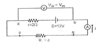
View SolutionThe figure shows a source (a battery) with an emf E of 12 V with an internal resistance r of 2Ω and an external resistance of 4Ω is added to complete the circuit. What are the voltmeter and ammeter readings
 View Solution
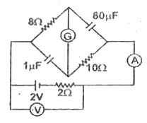
The ammeter (A) and voltmeter (V) in the given circuit are ideal but the galvanometer has a resistance of 2Ω In steady state
 View Solution
A galvanometer having 50 divisions provided with a variable shunt S is used to measure the current when connected in series with a resistance of 90Ω and a battery of internal resistance 10Ω. It is observed that when the shunt resistances are 10Oemga and 50Ω, the deflections are, respectively, 9 and 30 divisions. What is the resistance of the galvanometer
View SolutionA cell of emf 3.4V and internal resistance 3Ω is connected to an ammeter having resistance 2Ω and to an external resistance of 100Ω. When a voltmeter is connected across the 100Ω resistance, the ammeter reading is 0.04A. Find the voltage reading by the voltmeter and its resistance. Had the voltmeter been an ideal one what would have been its reading?
View Solution

