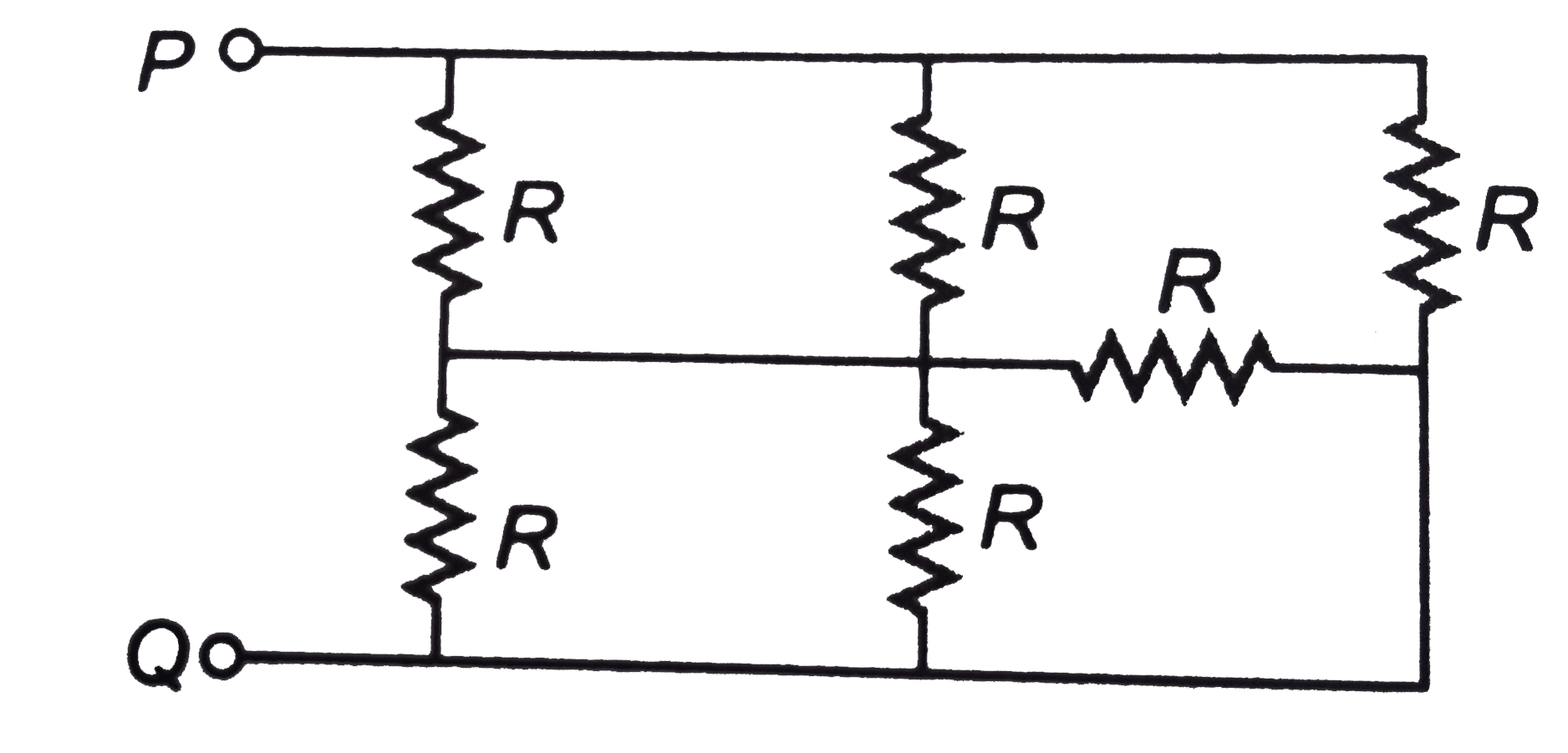
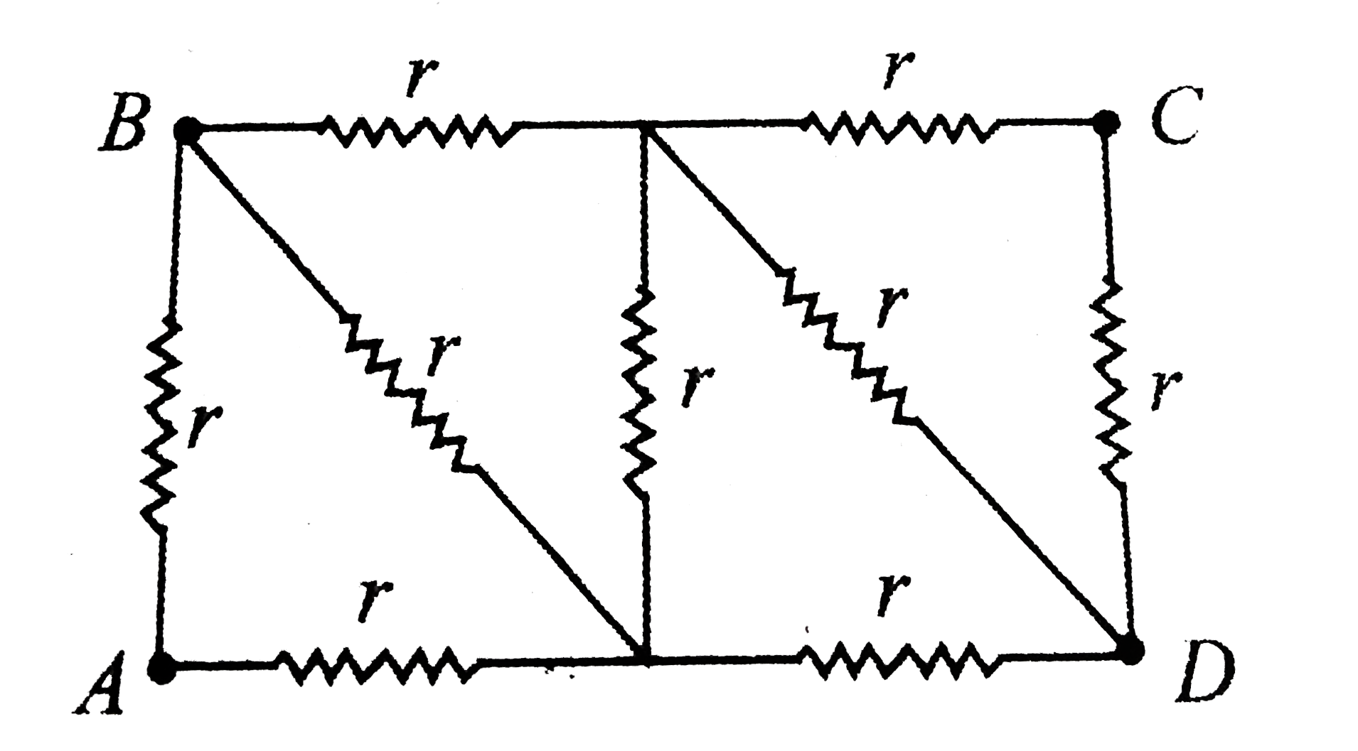
In the circuit shown in figure R=55Ω the equivalent resistance between the point P and Q is
30Ω
35Ω
55Ω
25Ω
The correct Answer is:D
Simple circuit is as shown in figure

Topper's Solved these Questions
- CURRENT ELECTRICITYBOOK - DC PANDEY ENGLISHCHAPTER - CURRENT ELECTRICITYEXERCISE - OBJECTIVE_TYPE
1 Videos
- CURRENT ELECTRICITYBOOK - DC PANDEY ENGLISHCHAPTER - CURRENT ELECTRICITYEXERCISE - Level 1 Subjective
53 Videos
- CURRENT ELECTRICITYBOOK - DC PANDEY ENGLISHCHAPTER - CURRENT ELECTRICITYEXERCISE - Level 1 Assertion And Reason
11 Videos
- COMMUNICATION SYSTEMBOOK - DC PANDEY ENGLISHCHAPTER - COMMUNICATION SYSTEMEXERCISE - Subjective
11 Videos
- ELECTROMAGNETIC INDUCTIONBOOK - DC PANDEY ENGLISHCHAPTER - ELECTROMAGNETIC INDUCTIONEXERCISE - Medical entrances gallery
25 Videos
Similar Questions
In the circuit shown in Fig. (b) calculate the equivalent resistance between the points A and B.

View SolutionEquivalent resistance between the points A and B (in Ω)
 .
.
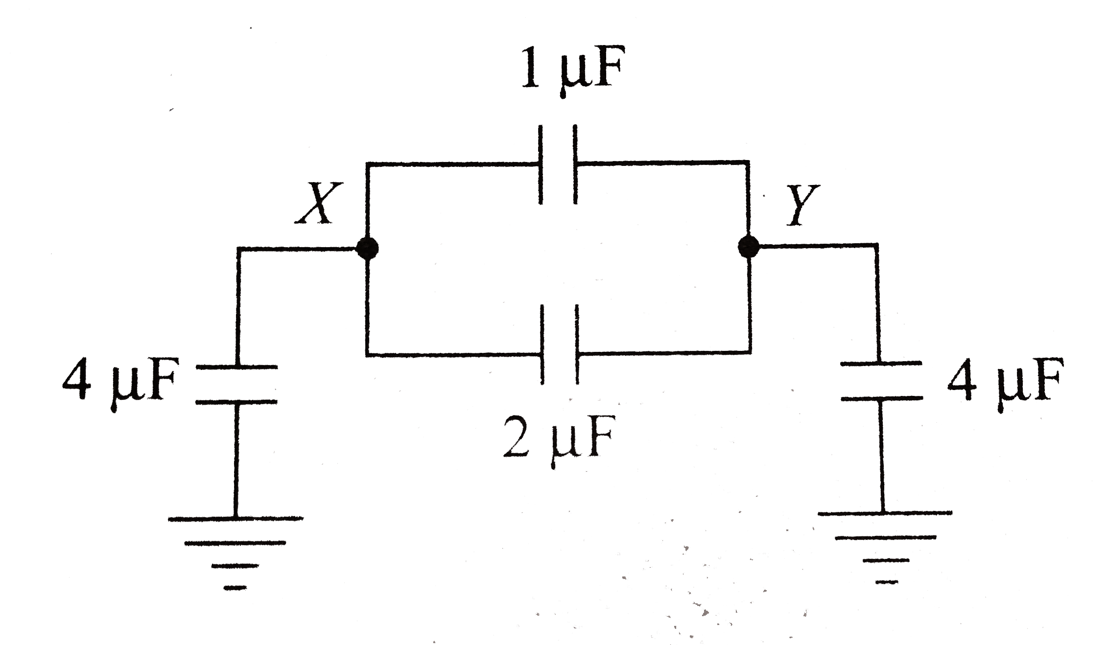
View SolutionIn the circuit shown in figure, the equivalent capacitance between the points X and Y is
View SolutionIn the given figure, equivalent resistance between points P and Q is
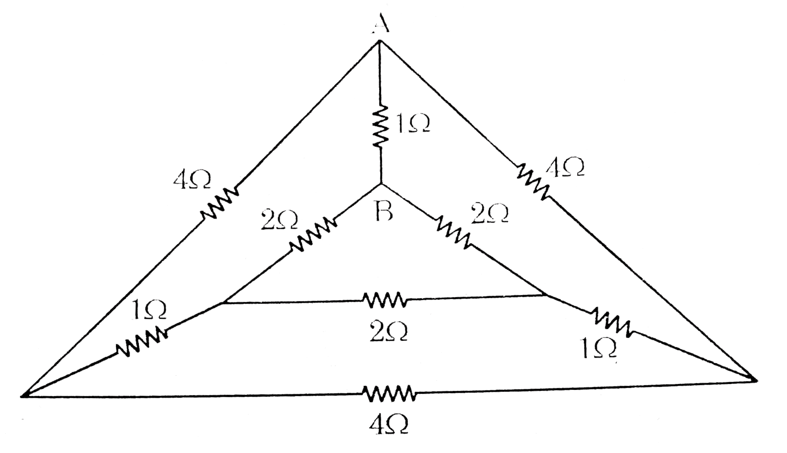
View SolutionConsider the circuit as shown in figure. The equivalent resistance between A and B is
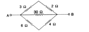
View SolutionCalculate the equivalent resistance between the points A and B in Fig.
View SolutionFor the circuit shown in fig. the equivalent resistance between A and C is
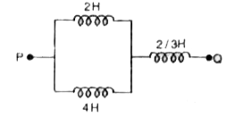
View SolutionThe equivalent inductance between points P and Q in figure is :
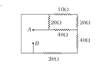
View SolutionIn the circuit shown in figure, the equivalent resistance between A and B is __________ Ω.
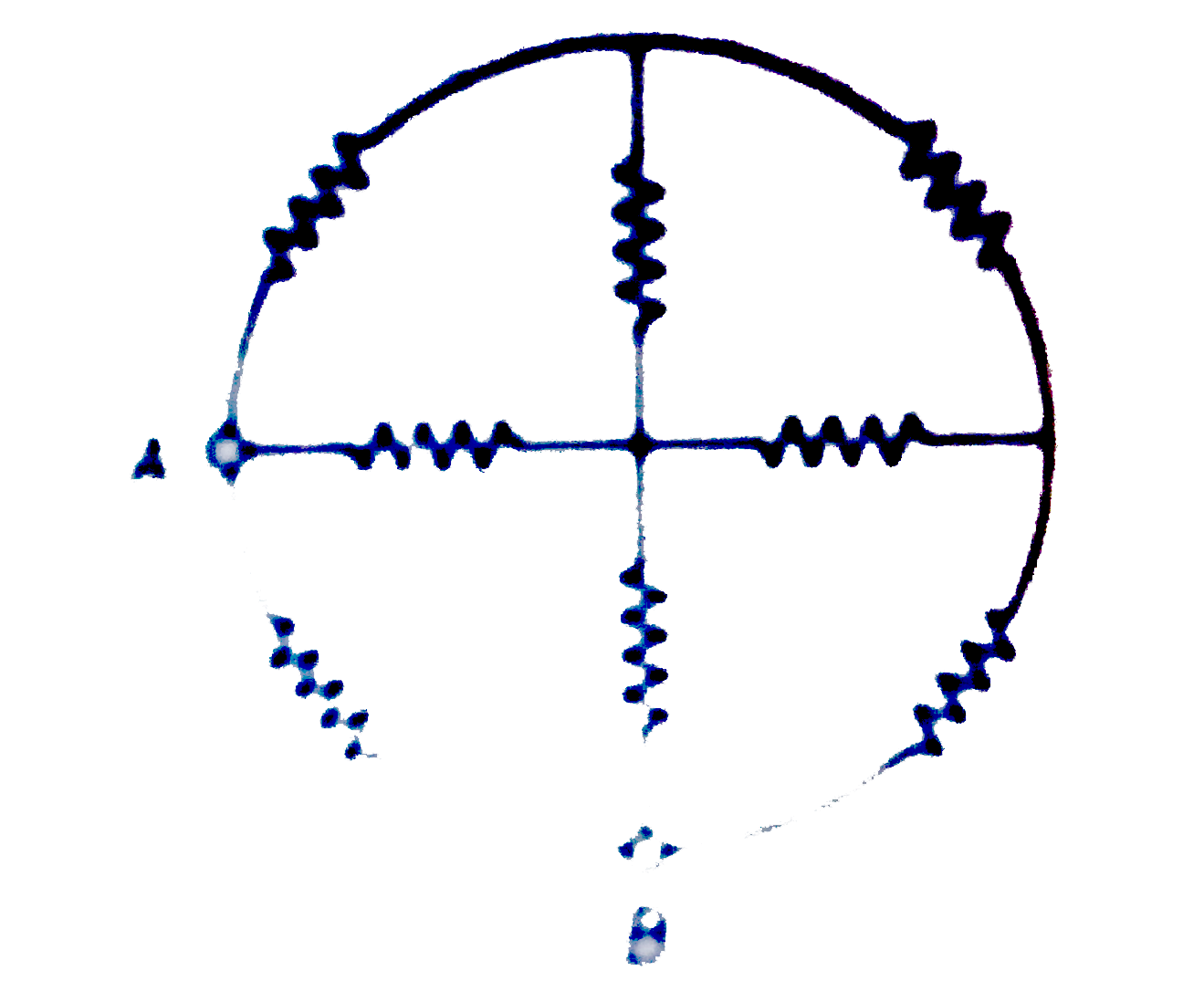
View SolutionEight resistances each of resistance 5Ω are connected in the circuit as shown in figure. The equivalent resistance between A and B is
View Solution

