A capacitor C is connected to two equal resistances as shown in the figure. Consider the following statemets
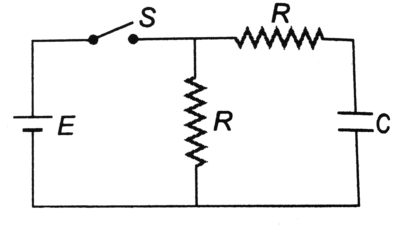
i. At the time of charging of capacitor time constant of the circuit is CR
ii. At the time of discharging of the capacitor the time constant of the circuit is CR
iii. At the time of discharging of the capacitor the time constant of the circuit is 2CR
iv At the time of charging of the capacitor the time constant of the circuit is 2CR
statements i and ii only are correct
statements ii and iii only are correct
statements iii and iv only are correct
statements i and iii only are correct
The correct Answer is:C
During charging capacitor and resistance of its wire are indenpendently connected with the battery. Hence
τC=CR
During discharging capacitor is discharged through both resistors (in series). Hence
τC=C(2R)=2CR
Topper's Solved these Questions
- CAPACITORSBOOK - DC PANDEY ENGLISHCHAPTER - CAPACITORSEXERCISE - OBJECTIVE_TYPE
1 Video
- CAPACITORSBOOK - DC PANDEY ENGLISHCHAPTER - CAPACITORSEXERCISE - OBJECTIVE_TYPE
1 Video
- ATOMSBOOK - DC PANDEY ENGLISHCHAPTER - ATOMSEXERCISE - MEDICAL ENTRANCES GALLERY
42 Videos
- COMMUNICATION SYSTEMBOOK - DC PANDEY ENGLISHCHAPTER - COMMUNICATION SYSTEMEXERCISE - Subjective
11 Videos
Similar Questions
The time constant of C-R circuit is
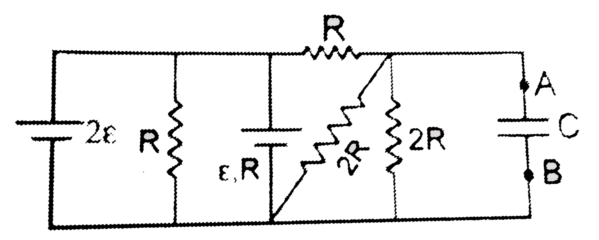
View SolutionThe time constant of the circuit shown is :
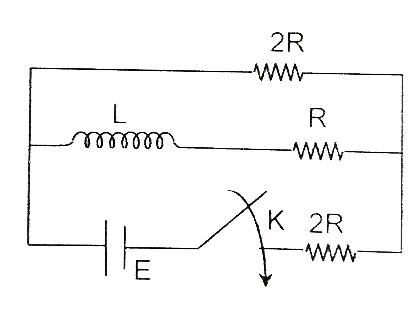
View SolutionTime constant of LR circuit will be
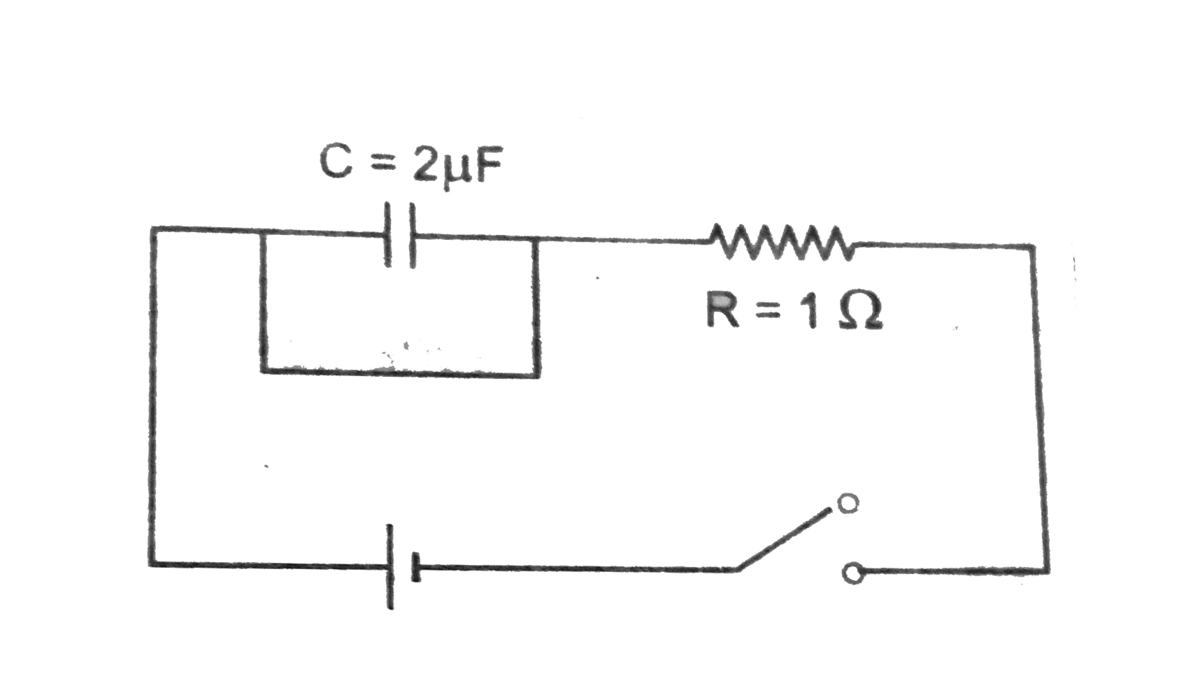
View SolutionThe capacitive time constant of the RC circuit shown in the figure.
View SolutionThe time constant of the circuit shown in the figure is
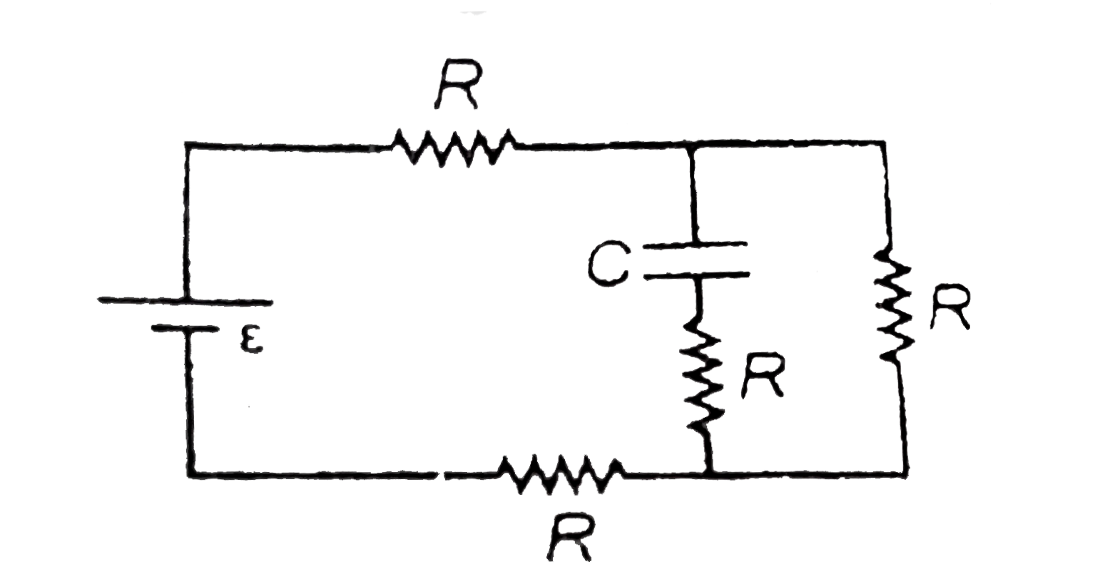
View SolutionIn the transient circuit shown, the time constant of the circuit is :

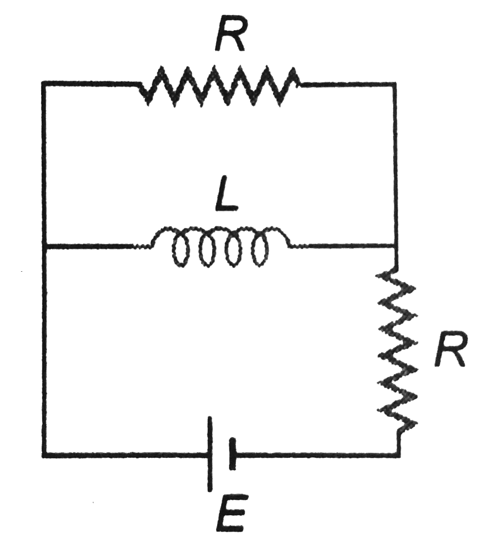
View SolutionThe figure shows an L−R circuit the time constant for the circuit is
View SolutionA capacitor C is connected to the two equal resistances as shown in fig. What is the ratio of the time constant during charging and discharging of the capacitance?
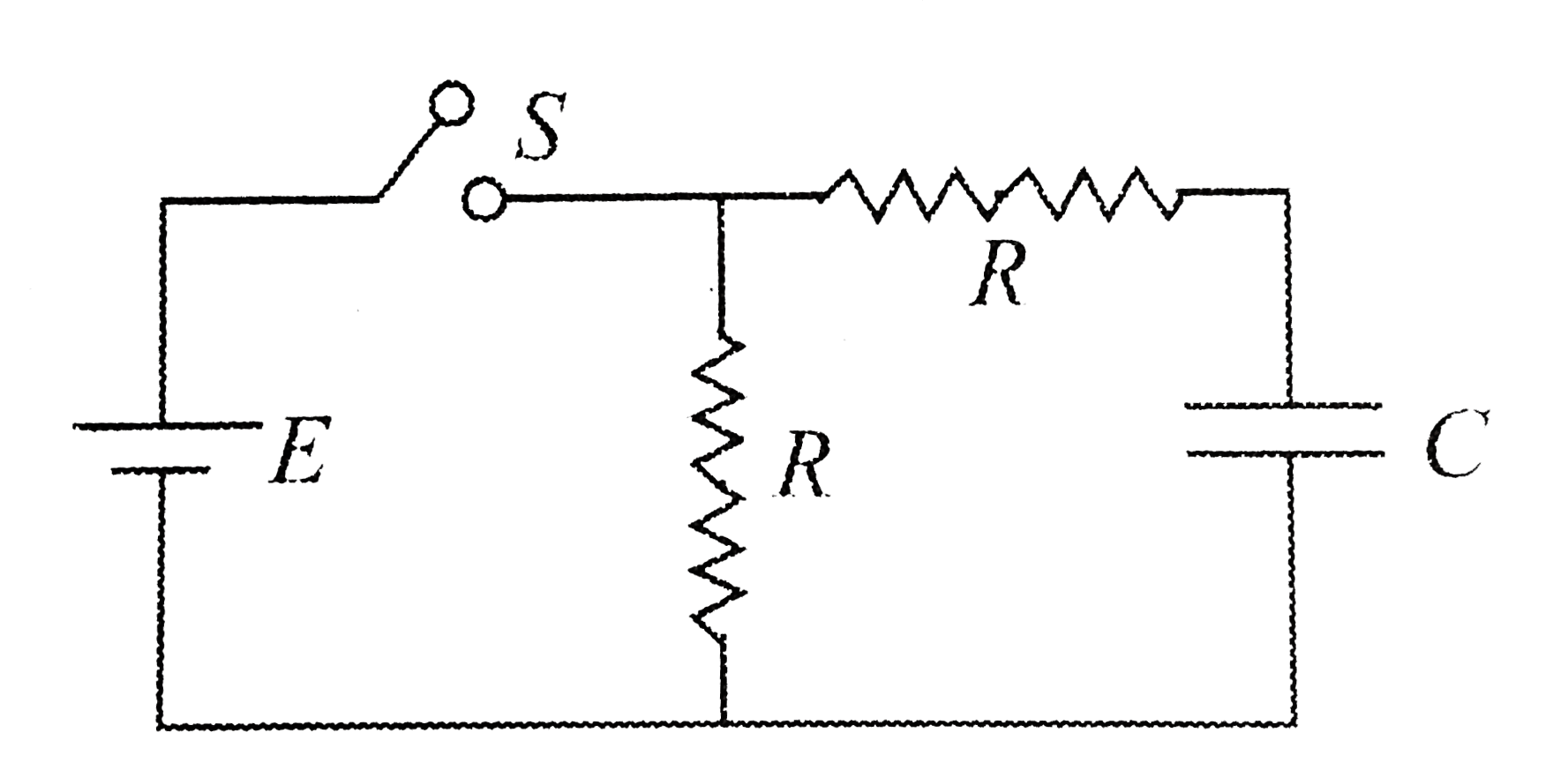
View SolutionThe time constant of charging of the capacitor charging of the capacitor shown in figure is

View SolutionDuring charging of capacitor in the circuit shown,

Circuit current versus time graph is
View Solution