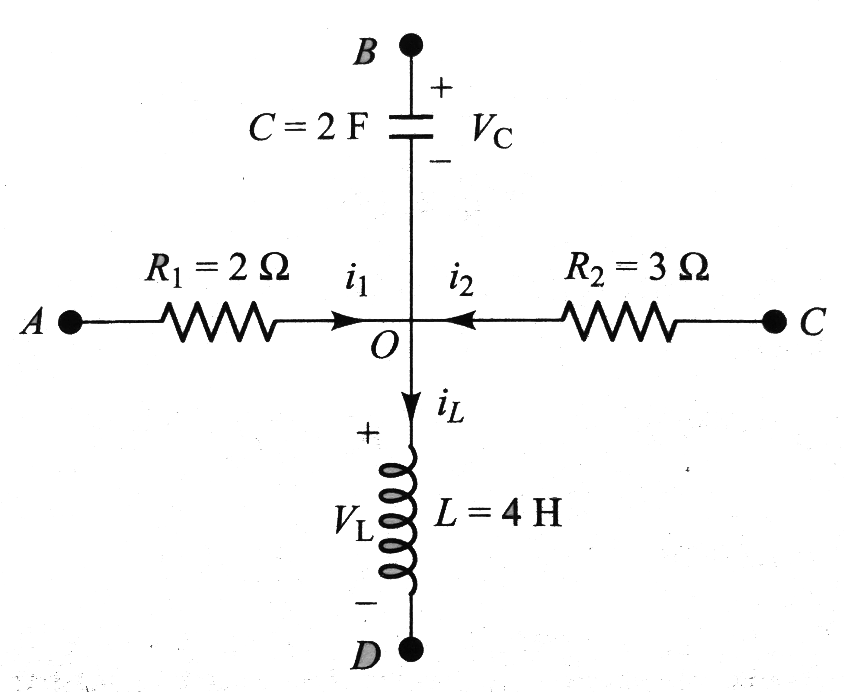
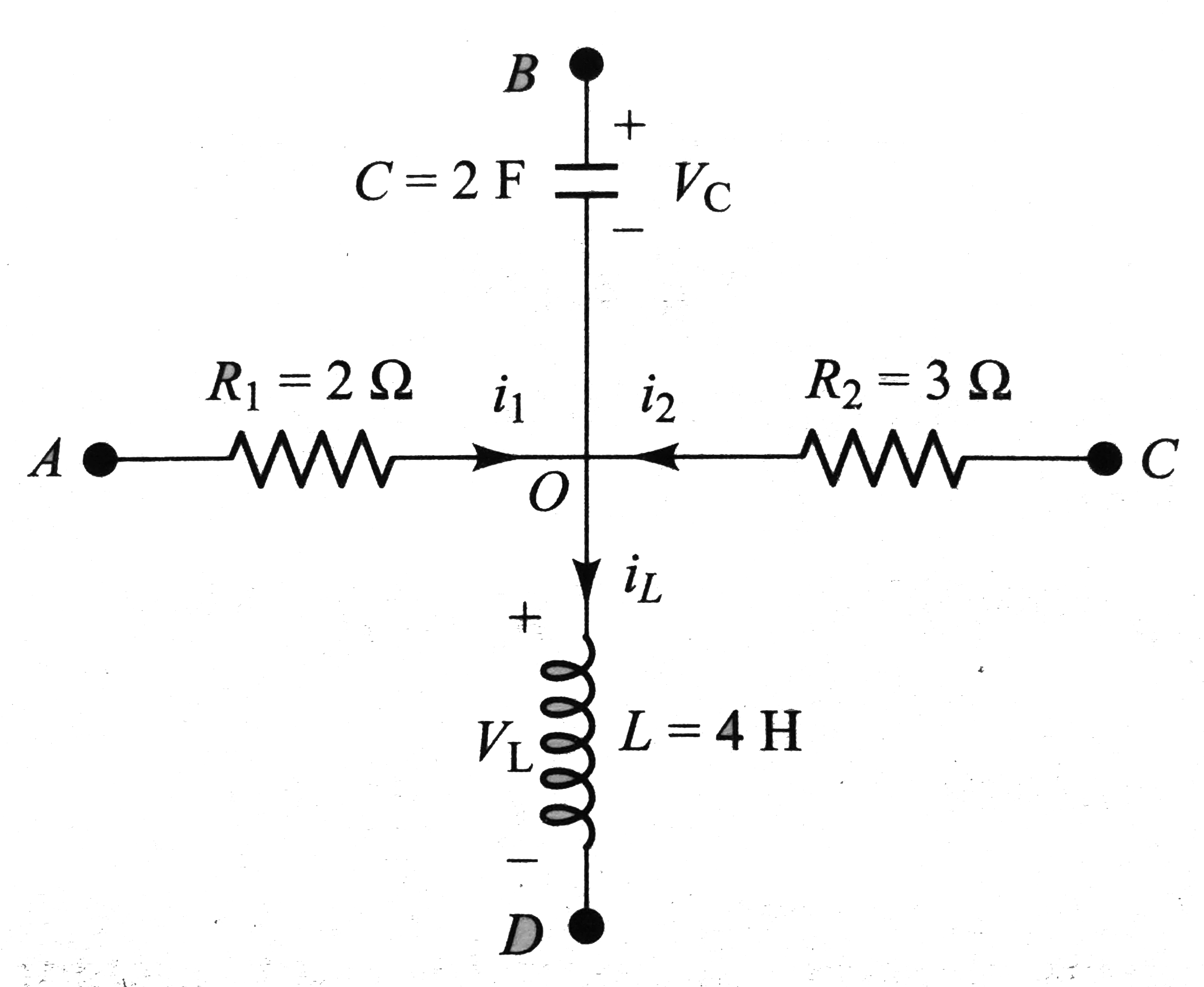
In the Figure shown i1=10e−2tA,i2=4A and VC=3e−2tV. Determine
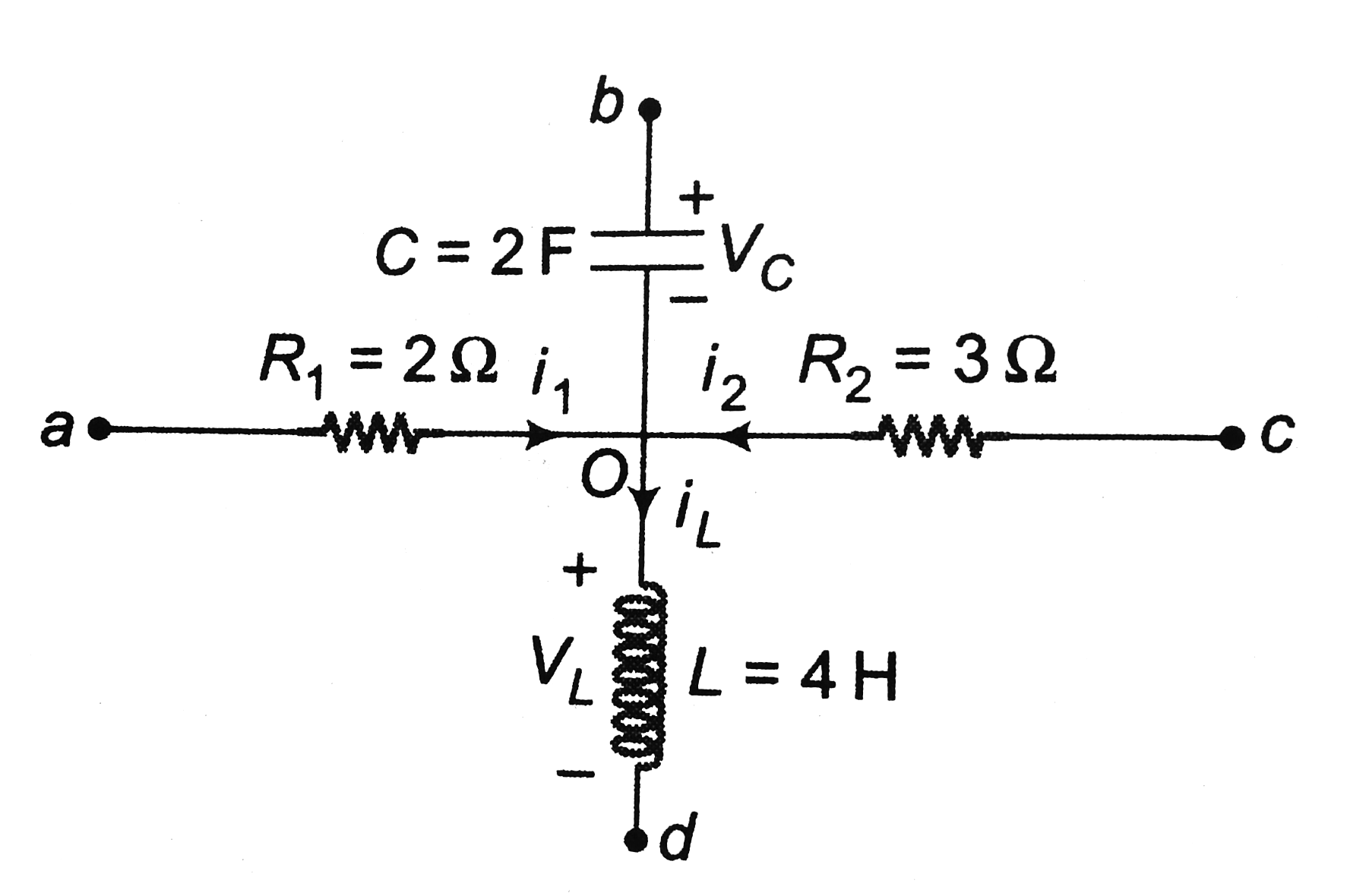
a. iL and VL b. Vac,Vab,Vcd
a. Charge stored in the capacitor at time t,
q=CVC
=(2)(3e−2t)
=6e−2tC
∴ic=dqdt=12e−2tA
(Direction of current is form b to O)
Applying junction rule at O,
iL=i1+i2+ie=10e−2t+4−12e−2t
=(4−2e−2t)A
[2+2(1−e−2t)]A
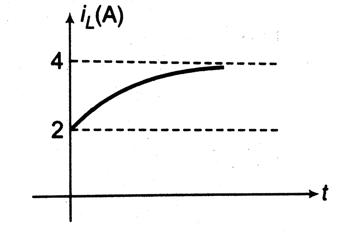
iL versus time graph is as show in figure.
iL increases from 2A to 4A exponentially .
VL=VOd=LdiLdt=(4)ddt(4−2−2t)
=16e−2tV
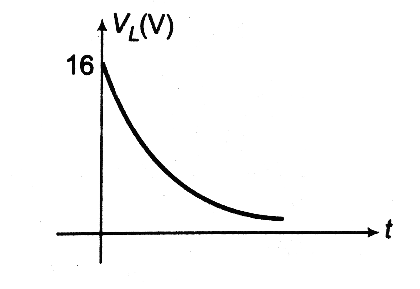
VL versus time graph is an shown in figure.
VL decreases exponentially from 16V to 0.
b. Vac=Va−Vc
Va−i1R1+i2R2=Vc
∴Va−Vc=Vac=i1R11−i2R2
substituting the values we have
Vac=(10e−2t)(2)−(4)(3)
Vac=(20e−2t−12)V
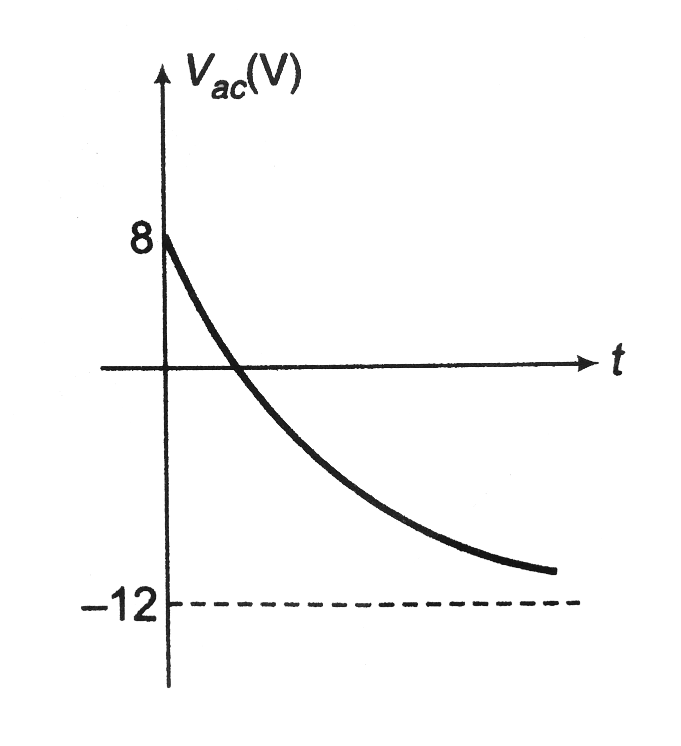
At t=0,Vac=8V and at t=∞,Vac=−12V
Therefore Vac decreases exponentially from 8 to −12V.
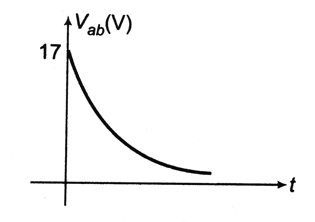
Vab=Va−Vb
Va−i1R1+VC=Vb
∴Va−Vb=Vab=i1R1−VC
Substituting the values , we have
Vab=(10e−2t)(2)=3e−2t
or Vab=17e−2tV
Thus Vab decreses exponentially from 17V to 0.
Vab versus t graph is shown in figure.
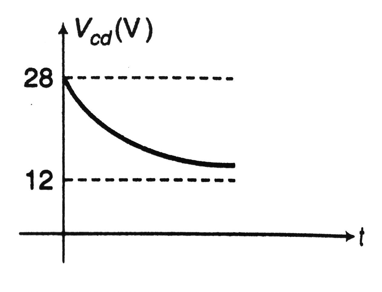
Vcd=VC−Vd
Vd−i2R2−VL=V4
∴Vc−Vd=Vcd=i2R2+VL
Substituting the values we have
Vcd=(4)(3)+16e−2t
Vcv=(12+16e−2t)V
At t=0,Vcd=28 and at t=∞,Vcd=12V
i.e. Vcd decreases exponentially from 28V to 12V
Vcd versus t graph is shown in figure.

Topper's Solved these Questions
- ELECTROMAGNETIC INDUCTIONBOOK - DC PANDEY ENGLISHCHAPTER - ELECTROMAGNETIC INDUCTIONEXERCISE - Example Type 3
4 Videos
- ELECTROMAGNETIC INDUCTIONBOOK - DC PANDEY ENGLISHCHAPTER - ELECTROMAGNETIC INDUCTIONEXERCISE - Example Type 4
2 Videos
- ELECTROMAGNETIC INDUCTIONBOOK - DC PANDEY ENGLISHCHAPTER - ELECTROMAGNETIC INDUCTIONEXERCISE - Medical entrances gallery
25 Videos
- CURRENT ELECTRICITYBOOK - DC PANDEY ENGLISHCHAPTER - CURRENT ELECTRICITYEXERCISE - Medical entrances gallery
97 Videos
- ELECTROMAGNETIC WAVESBOOK - DC PANDEY ENGLISHCHAPTER - ELECTROMAGNETIC WAVESEXERCISE - Sec C
22 Videos
Similar Questions
Knowledge Check
In the figure shown i=10e−4tA. Find VL and Vab
 A−40eVB40eVC40eVD−40eV
In the figure shown Vab at t=1 is

View SolutionIn Fig i1=10e−2tA, i2=4A, and VC=3e−2tV.
the vartiation of potential difference across A and C(VAC) with time can be respresented as
View SolutionIn Fig i1=10e−2tA, i2=4A, and VC=3e−2tV.
The variation of potential difference across C and D(VCD) with time can be expressed as
View SolutionIn the circuit shown in figure
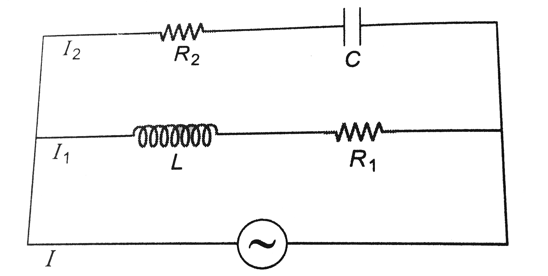
R1=30Ω,R2=40Ω,L=0.4H and C=13mF.
Find seven function of time I,I1,I2,VR1,VL,VR2 and VC. Also total power consumed in the circuit. In the given potential function V is in volts and omega rad/s V=200 sin(100t+30)
View SolutionIn the circuit shown in figure q varies with time t as q=(16t2). Here q is in coulomb and t in second.

Find Vab=(Va−Vb)att=3s
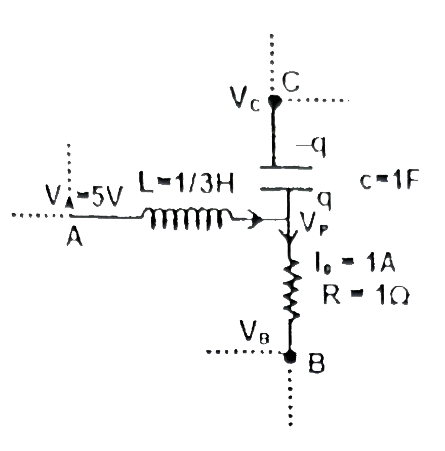
View SolutionGiven figure is the part of some circuit. Charge on the capacitor in the circuit is given by q=3(3−e−t), (coulomb) where t is time in seconds.
Let VA, VB and VC be the potentials of points A, B and C, respectively. At t=0 if VA=5V and a constant current i0=1Amp flows through R=1Ω, then find the VP (in volt)
View SolutionIn the figure shown, the reading of voltmeters are V1=40V,V2=40V and V3=10V. Find
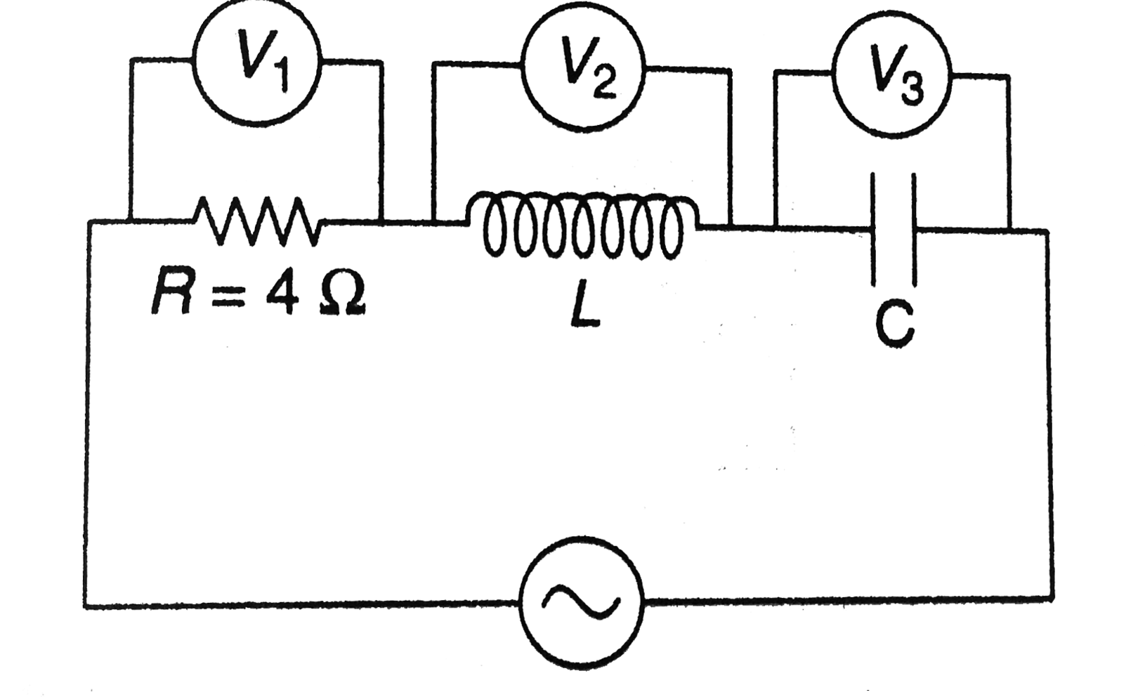
(a) the peak value of current
(b) the peak value of emf
(c) the value of L and C.
View Solution
