In the circuit diagram shown in the adjoining figure, the resultant capacitance between P and Q is
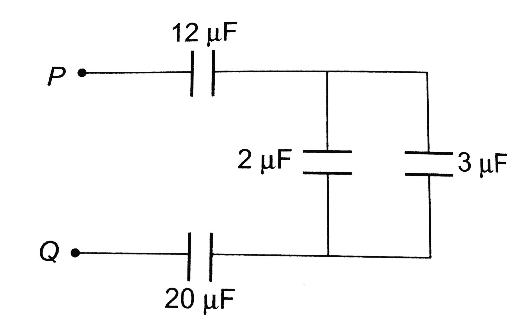
47μF
3μF
60μF
10μF
The correct Answer is:B
Step by step video & image solution for In the circuit diagram shown in the adjoining figure, the resultant capacitance between P and Q is by Physics experts to help you in doubts & scoring excellent marks in Class 12 exams.
Updated on:21/07/2023Topper's Solved these Questions
- ELECTROSTATIC POTENTIAL AND CAPACITORSBOOK - DC PANDEY ENGLISHCHAPTER - ELECTROSTATIC POTENTIAL AND CAPACITORSEXERCISE - (B) Chapter exercises
17 Videos
- ELECTROSTATIC POTENTIAL AND CAPACITORSBOOK - DC PANDEY ENGLISHCHAPTER - ELECTROSTATIC POTENTIAL AND CAPACITORSEXERCISE - (C) Chapter exercises
50 Videos
- ELECTROSTATIC POTENTIAL AND CAPACITORSBOOK - DC PANDEY ENGLISHCHAPTER - ELECTROSTATIC POTENTIAL AND CAPACITORSEXERCISE - Check point 2.5
20 Videos
- ELECTROMAGNETIC WAVESBOOK - DC PANDEY ENGLISHCHAPTER - ELECTROMAGNETIC WAVESEXERCISE - Sec C
22 Videos
- ELECTROSTATICSBOOK - DC PANDEY ENGLISHCHAPTER - ELECTROSTATICSEXERCISE - Medical entrances gallery
37 Videos
Similar Questions
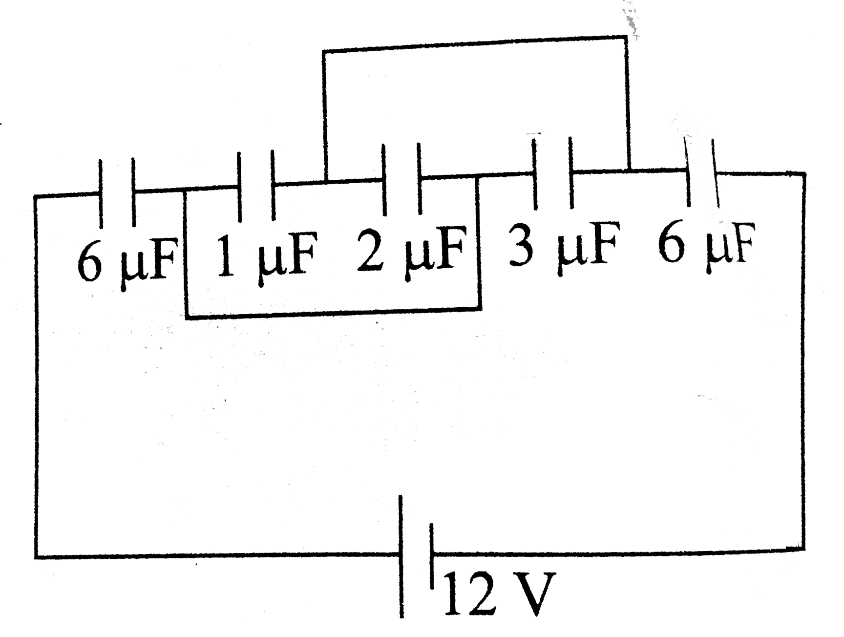
In the circuit diagram shown in Figure,
 .
.
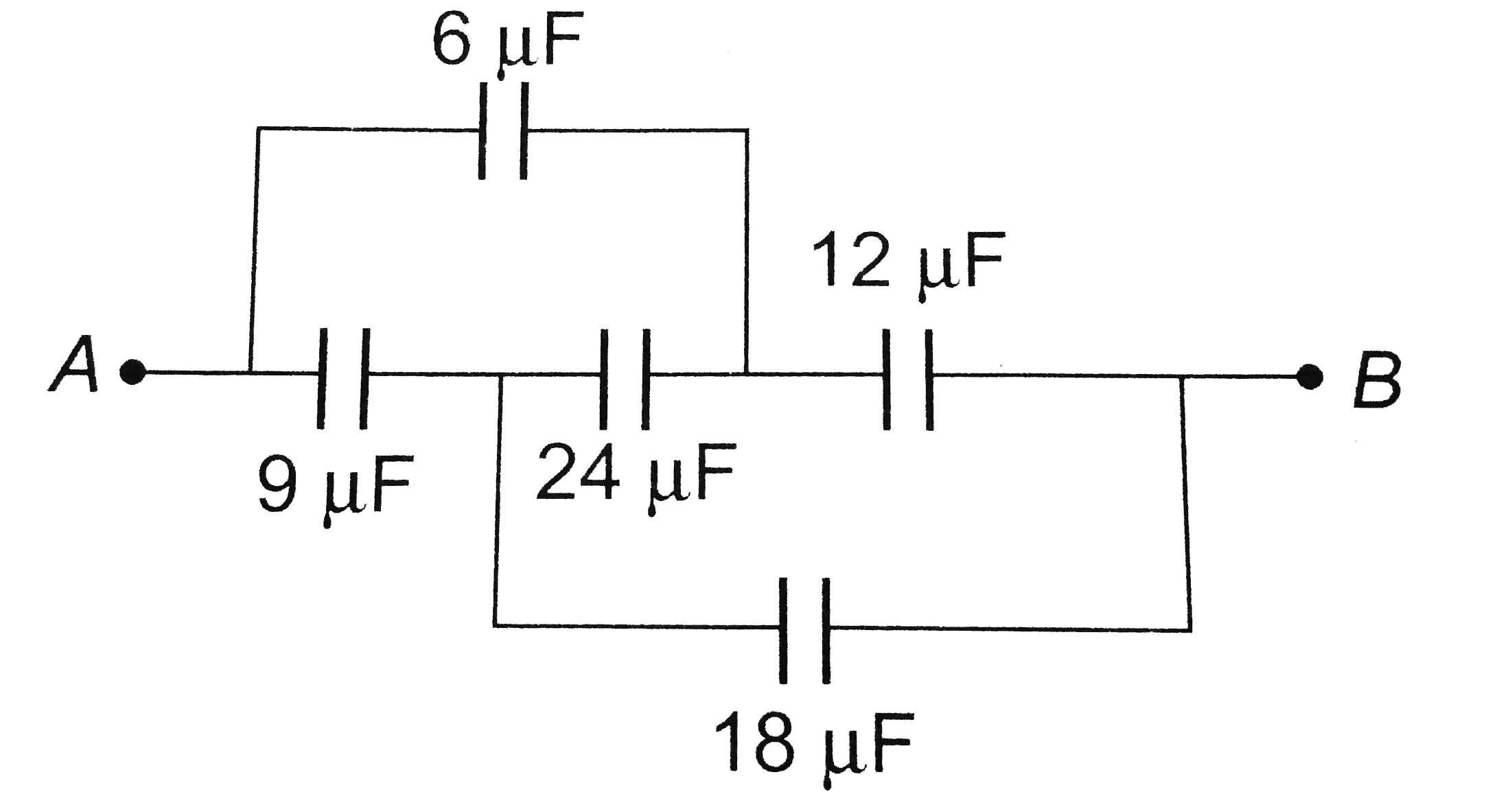
View SolutionIn the connection shown in the adjoining figure, the equivalent capacity between A and B will be
View SolutionIn the network of resistors shown in the adjoining figure, the equivalent resistance between A and B is

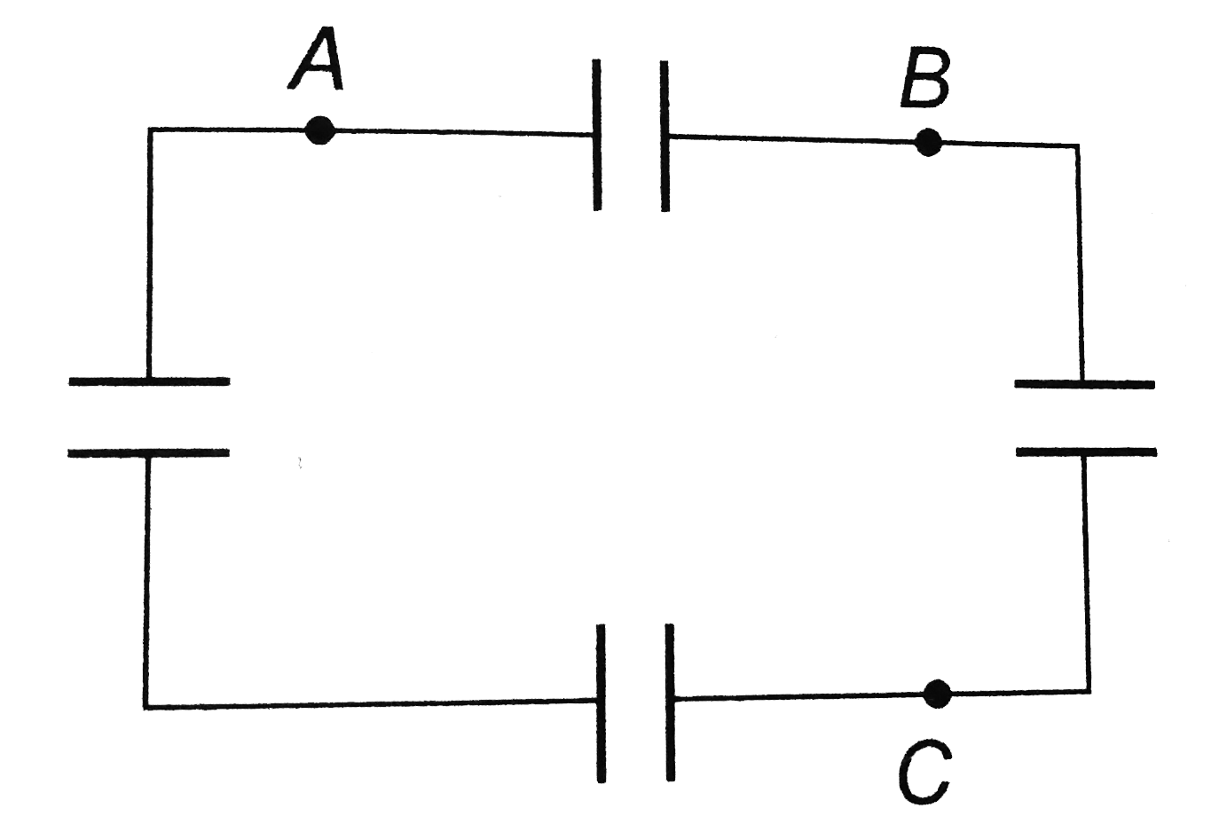
View SolutionFour capacitors of each of capacity 3μF are connected as shown in the adjoining figure. The ratio of equivalent capacitance between A and B and between A and C will be
View SolutionIn the circuit as shown in the figure the effective capacitance between A and B is
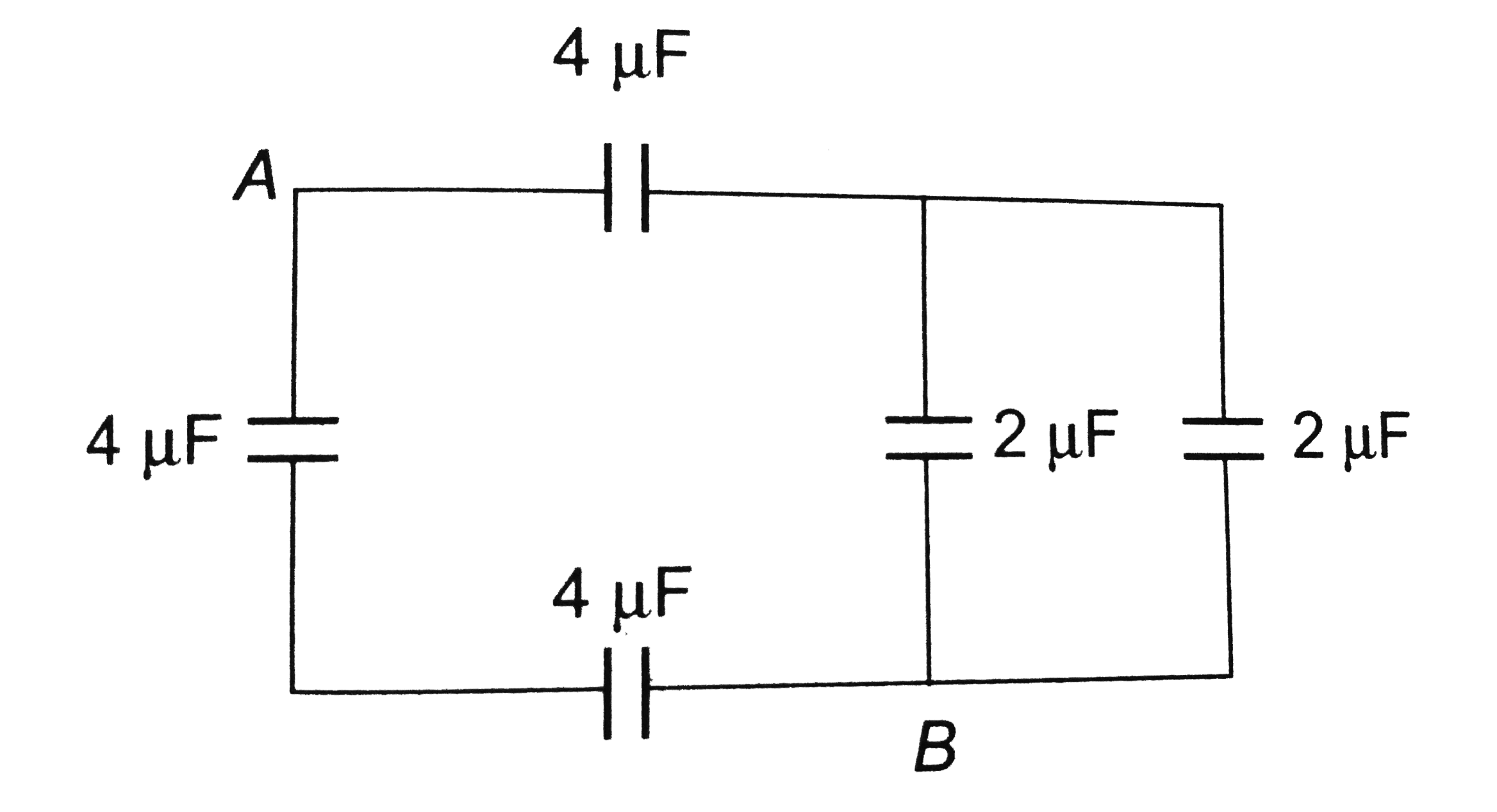
View SolutionIn the circuit as shown in the figure the effective capacitance between A and B is

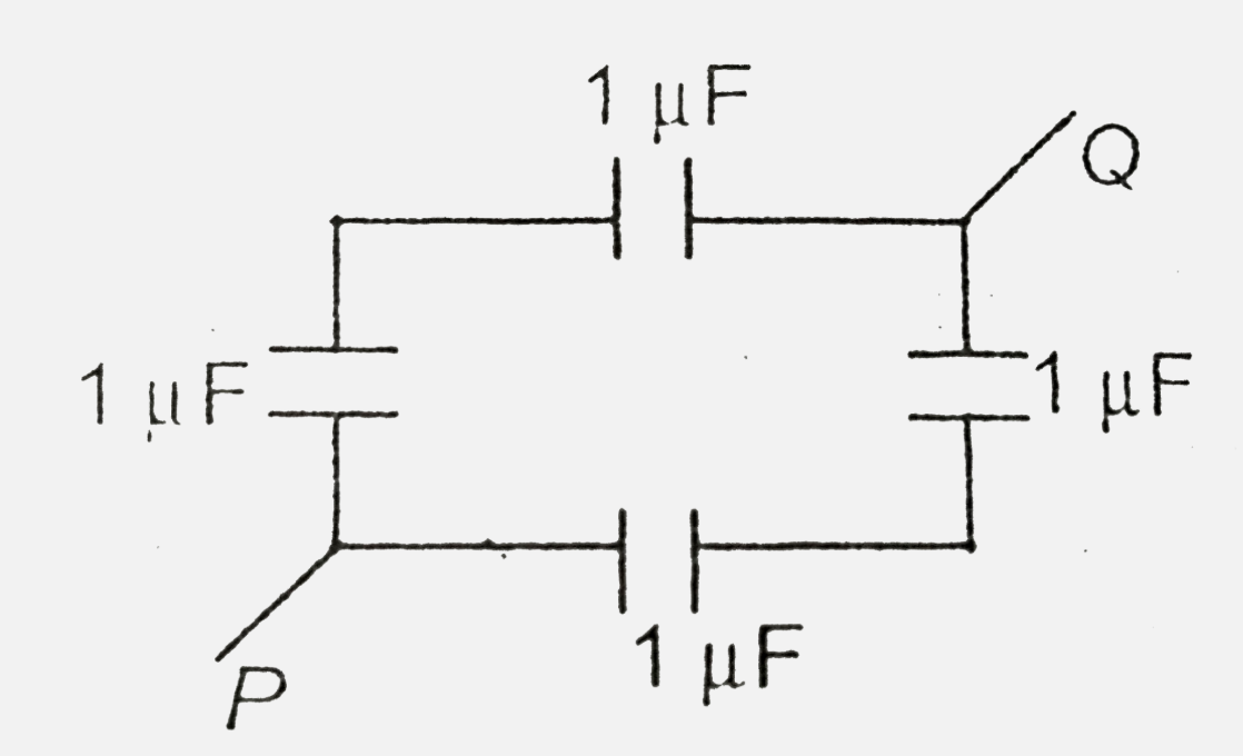
View SolutionFour capacitors are connected as shown in the figure. The equivalent capacitance between P and Q is
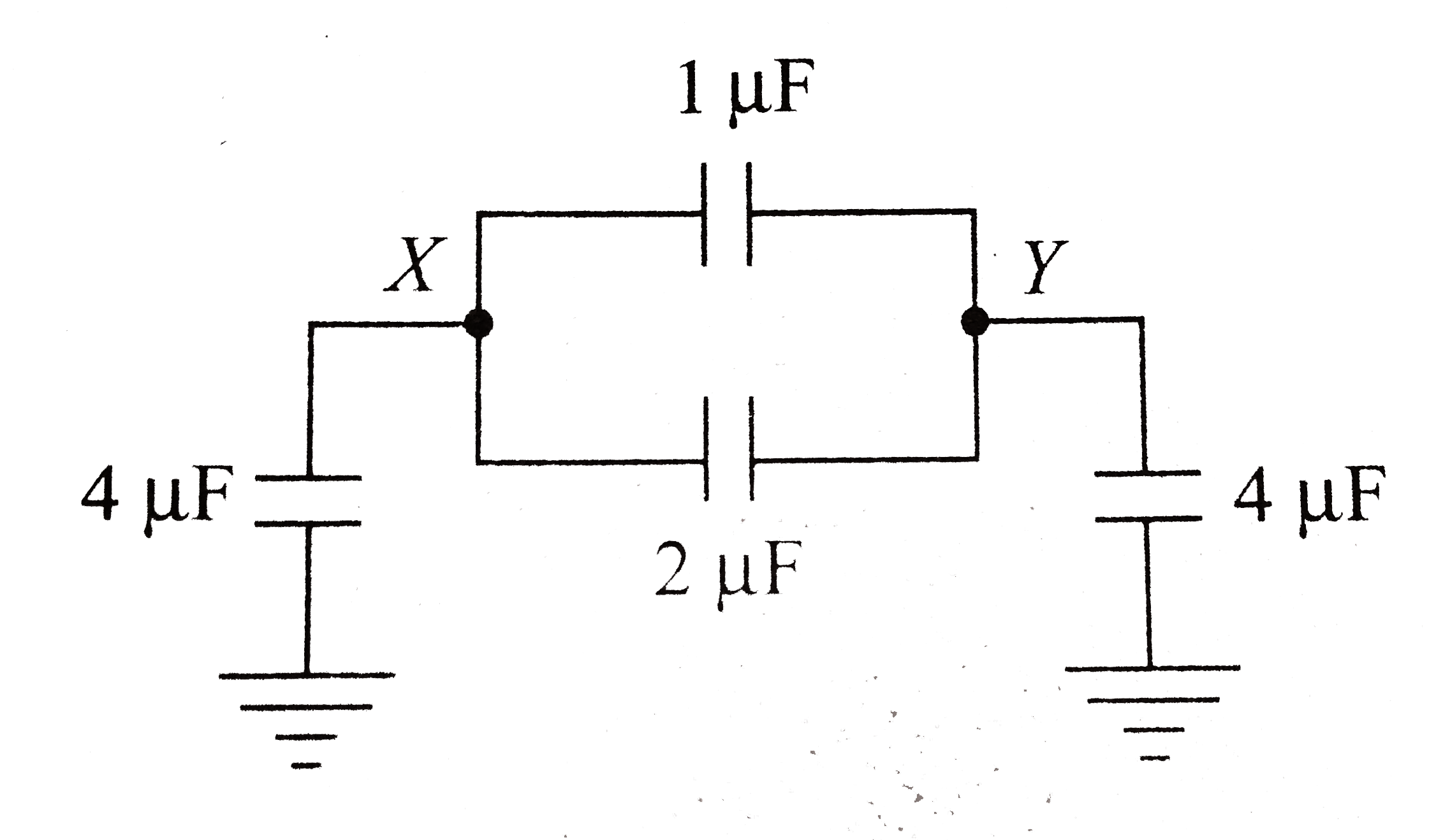
View SolutionIn the circuit shown in figure, the equivalent capacitance between the points X and Y is
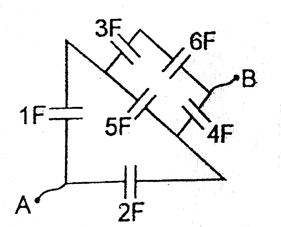
View SolutionIn the figure shown the equivalent capacitance between 'A' and 'B' is :
View SolutionIn the pure inductive circuit, the curves between frequency f and reciprocal of inductive reactance 1/XL is
View Solution
