A capacitor of 2μF is charged as shown in the figure. When the switch S is turned to position 2, the percentage of its stored energy dissipated is

20%
75%
80%
0%
The correct Answer is:C
Step by step video & image solution for A capacitor of 2 muF is charged as shown in the figure. When the switch S is turned to position 2, the percentage of its stored energy dissipated is by Physics experts to help you in doubts & scoring excellent marks in Class 12 exams.
Updated on:21/07/2023Topper's Solved these Questions
- ELECTROSTATIC POTENTIAL AND CAPACITORSBOOK - DC PANDEY ENGLISHCHAPTER - ELECTROSTATIC POTENTIAL AND CAPACITORSEXERCISE - (B) Chapter exercises
17 Videos
- ELECTROMAGNETIC WAVESBOOK - DC PANDEY ENGLISHCHAPTER - ELECTROMAGNETIC WAVESEXERCISE - Sec C
22 Videos
- ELECTROSTATICSBOOK - DC PANDEY ENGLISHCHAPTER - ELECTROSTATICSEXERCISE - Medical entrances gallery
37 Videos
Similar Questions
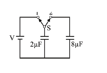
A capacitor of 2μF is charged as shown in the diagram. When the switch S is turned to position 2, the percentage of its stored energy dissipated is:
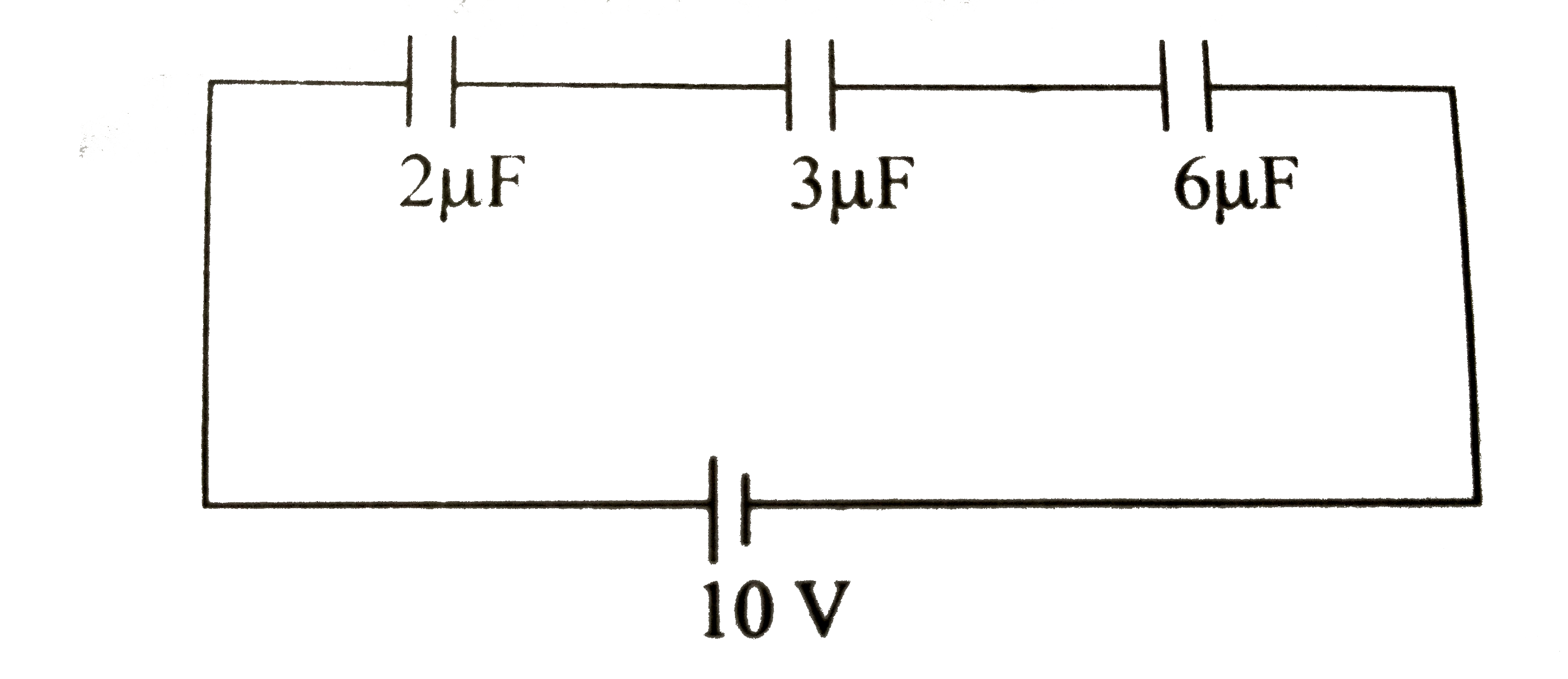
View SolutionThe charge on 3μF capacitor shown in the figure is
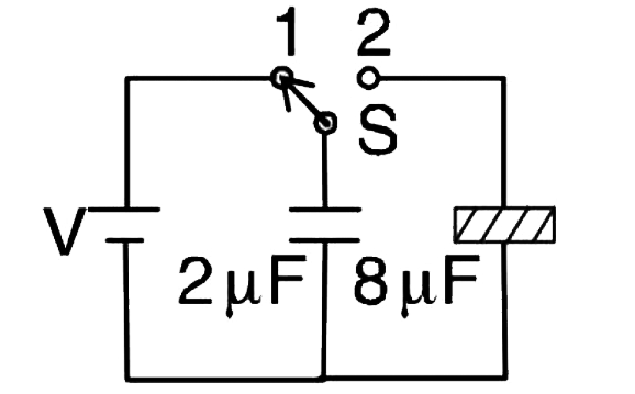
View SolutionA 2μF capacitor is charged as shown in the figure. The percentage of its stored energy disispated after the switch S is turned to poistion 2 is
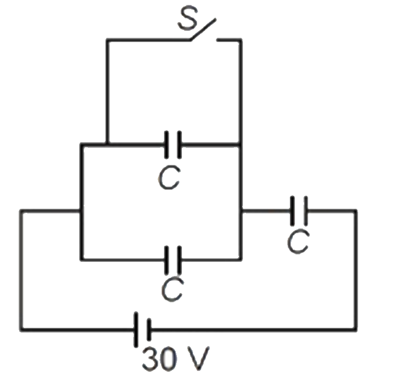
View SolutionThree capacitors each of capacitance C=2μF are connected with a battery of emf 30 V as shown in the figure . When the switch S is closed , the heat generated in the circuit will be
View SolutionFor the circuit shown in the figure, find the charge stored on capacitor in steady state.
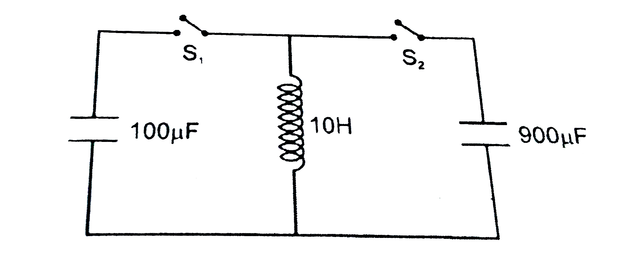
View SolutionInitially the 900μF capacitor is charged to 100 V and the 100μF capacitor is uncharged in the figure shown. Then the switch S2 is closed for a time t1, after which it is opened and at the same instant switch S1 is closed for a time t2 and then opened. It is now found that the 100μF capacitor is charged to 300 V. If t1andt2 minimum possible values of the time intervals, then findout t1t2
View SolutionTwo capacitors A and B are connected in series with a battery as shown in the figure. When the switch S is closed and the two capacitors get charged fully, then
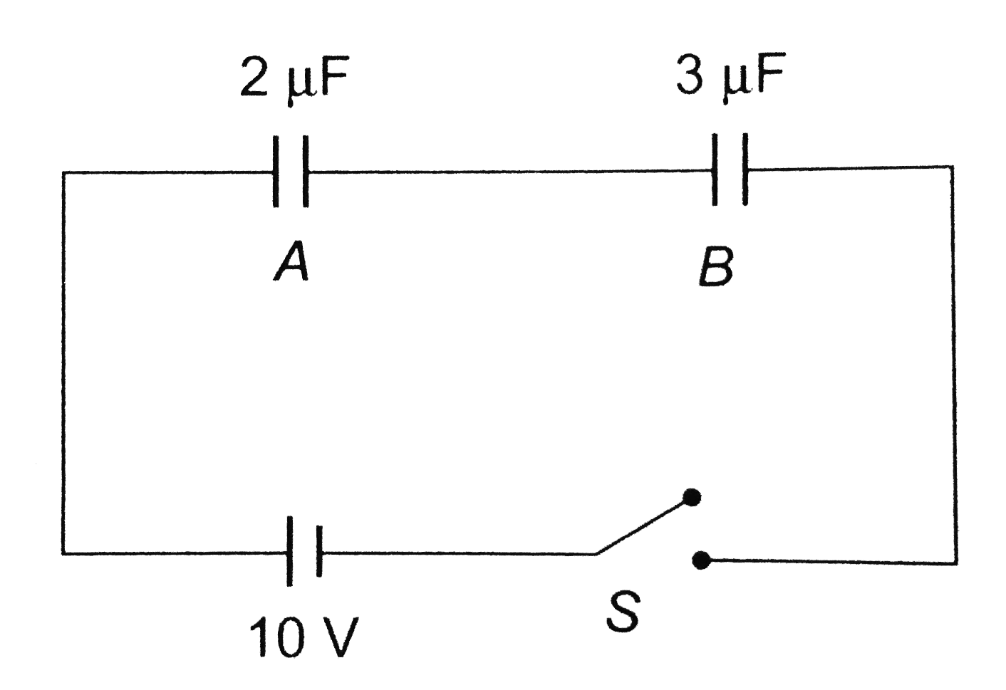
View SolutionTwo capacitors A and B are connected in series with a battery as shown in the figure. When the switch S is closed and the two capacitors get charged fully, then

View SolutionTwo capacitors A and B are connected in series with a battery as shown in the figure. When the switch S is closed and the two capacitors get charged fully, then

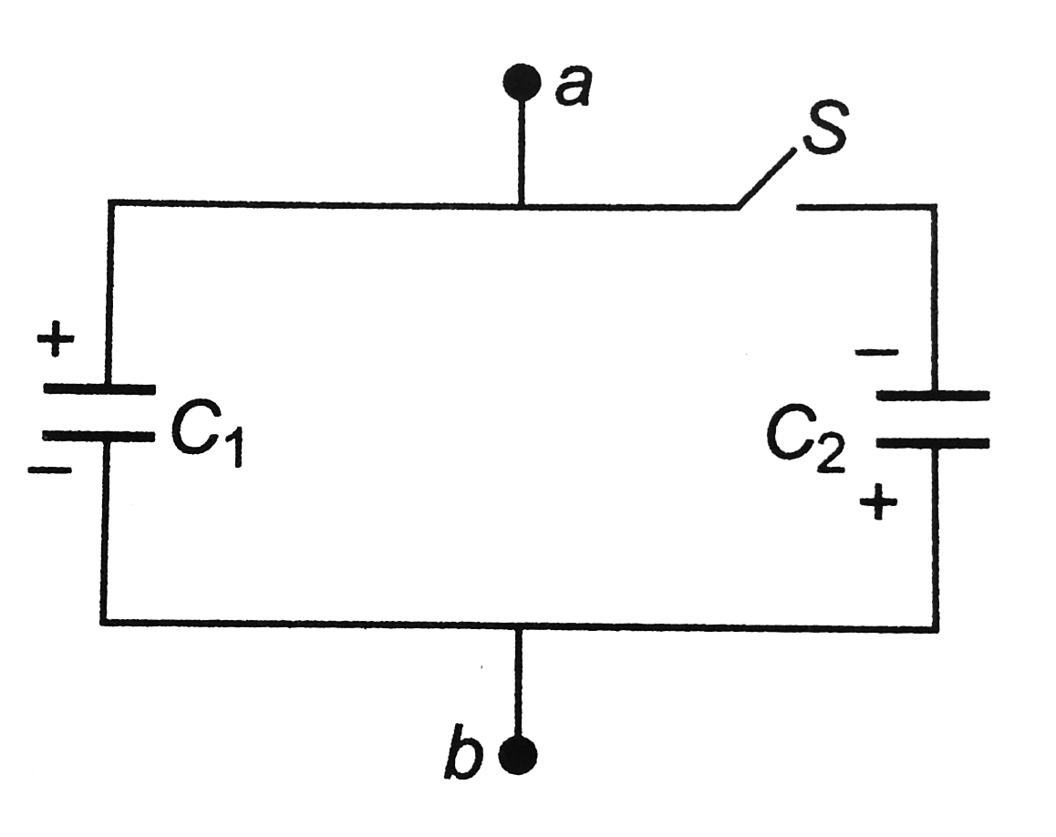
View SolutionTwo capacitors C1=1μF and C2=3μF each are charged to a potential difference of 100V but with opposite polarity as shown in the figure. When the switch S is closed, the new potential difference between the points a and b is
View Solution
