In the circuit shown, the currents i1 and i2 are
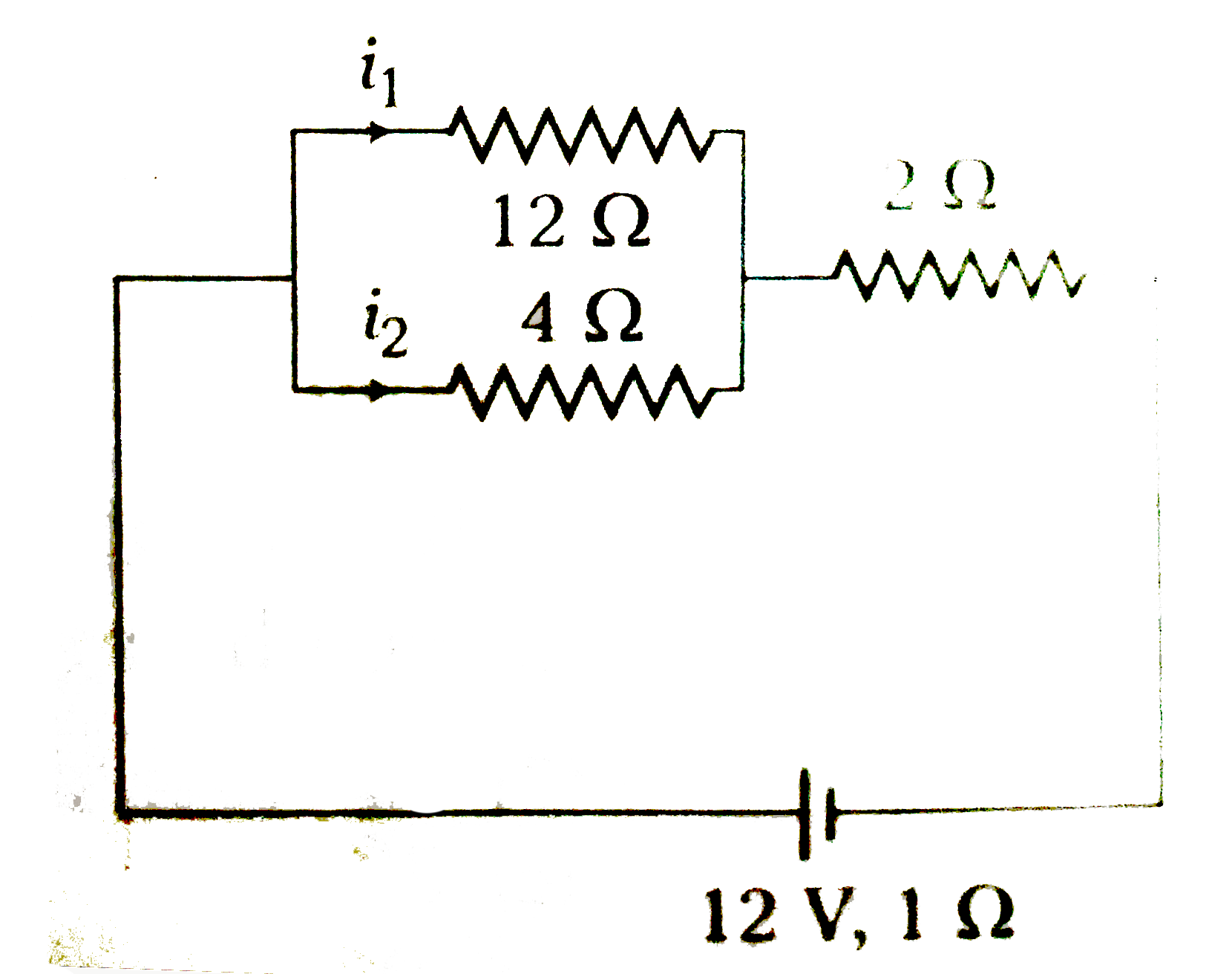
i1=1.5A,i2=0.5A
i1=0.5A,i2=1.5A
i1=1A.i2=3A
i1=3A,i2=1A
The correct Answer is:B
Step by step video & image solution for In the circuit shown, the currents i_(1) and i_(2) are by Physics experts to help you in doubts & scoring excellent marks in Class 12 exams.
Updated on:21/07/2023Topper's Solved these Questions
- CURRENT ELECTRICITYBOOK - DC PANDEY ENGLISHCHAPTER - CURRENT ELECTRICITYEXERCISE - B. Assertion and reason
18 Videos
- CURRENT ELECTRICITYBOOK - DC PANDEY ENGLISHCHAPTER - CURRENT ELECTRICITYEXERCISE - Match the columns
4 Videos
- CURRENT ELECTRICITYBOOK - DC PANDEY ENGLISHCHAPTER - CURRENT ELECTRICITYEXERCISE - Check point
70 Videos
- COMMUNICATION SYSTEMBOOK - DC PANDEY ENGLISHCHAPTER - COMMUNICATION SYSTEMEXERCISE - Subjective
11 Videos
- ELECTROMAGNETIC INDUCTIONBOOK - DC PANDEY ENGLISHCHAPTER - ELECTROMAGNETIC INDUCTIONEXERCISE - Medical entrances gallery
25 Videos
Similar Questions
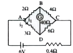
A balanced wheatstone bridge is shown the values of currents i1 and i2 are
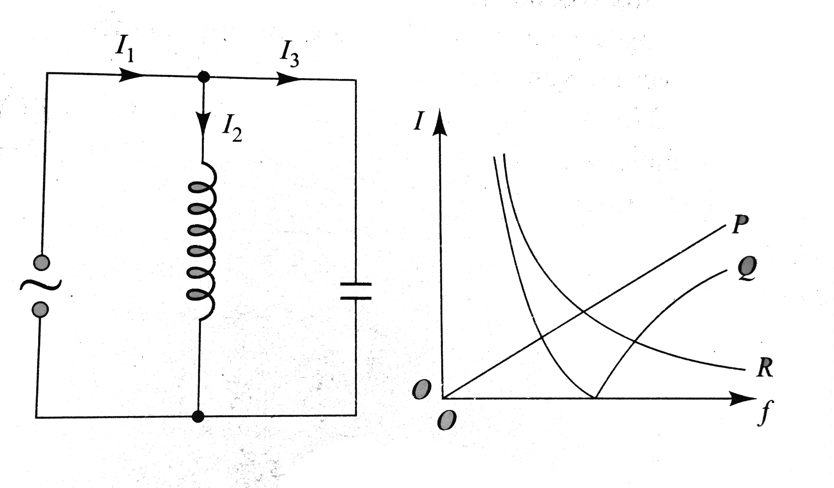
View SolutionIn the circuit shown if fig, the rms currents (I1),(I2) and(I3) are altered by varying the frequency f of the oscillator. The output voltage of the oscillator remains sinusoidal and has a fixed amplitude.
When curves in figure correctly indicate the variation with frequency of the currents (I1),(I2),and(I3).
View Solution
Knowledge Check
In the circuit shown, the value of currents I1,I2andI3 are
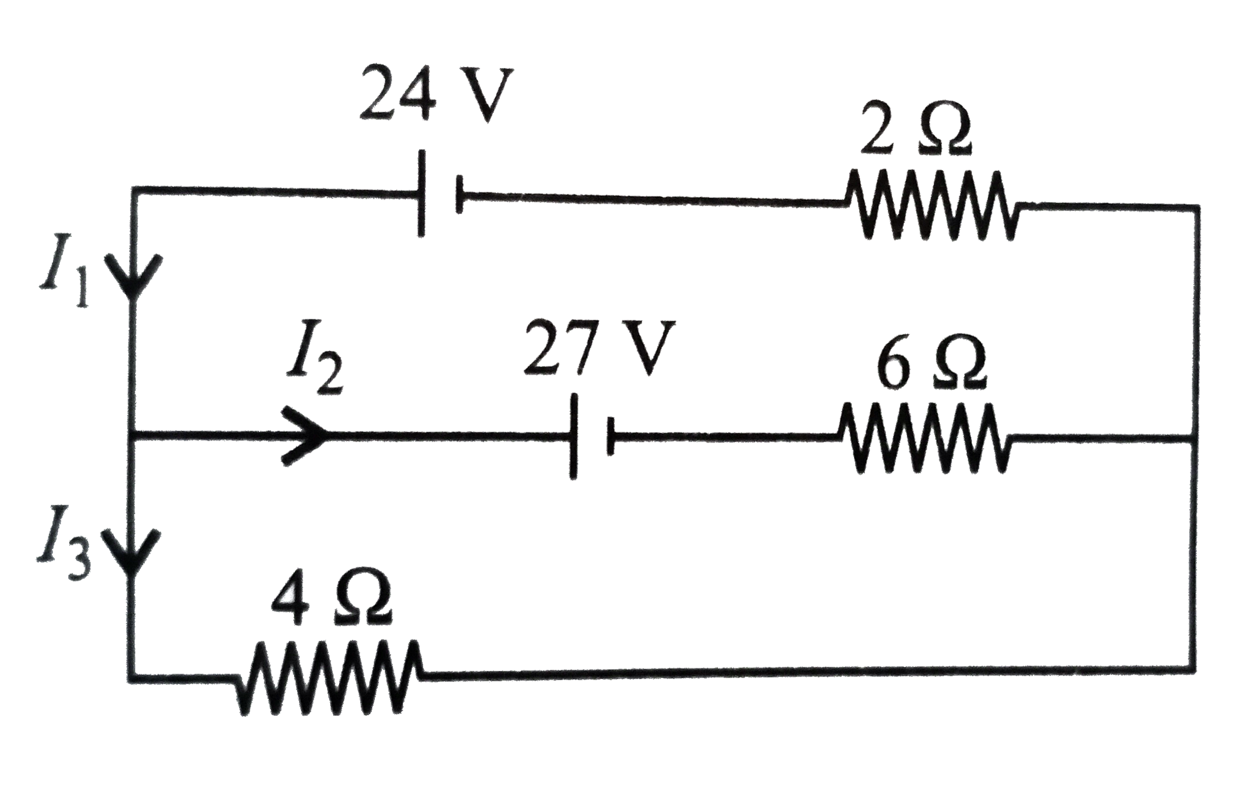 A3A,−3A2A,92AB92A,−32AC5A,4A,−3AD7A,54A,92A
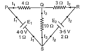
In the circuit shown in figure below, E1 and E2 are batteries having emfs 4.0 V and 3.5 V respectively and internal resistance 1Ω and 2Ω respectively. Using Kirchhoff.s laws, calculate currents : I1,I2 and I3.
View SolutionIn the circuit shown in figure below, E1 and E2 are two cells having emf 2 V and 3 V respectively and negligible internal resistances. Applying Kirchhoff.s laws of electrical networks, find the values of currents I1 and I2.
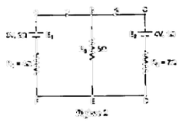
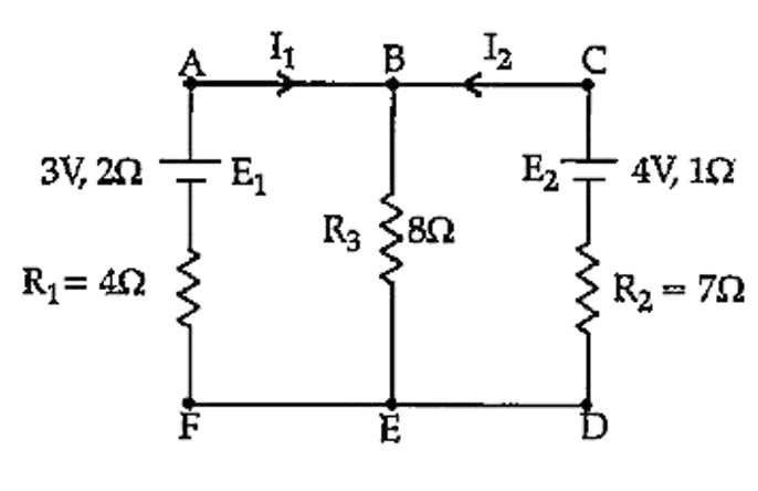
View SolutionE1andE2 are two batteries having emfs of 3V and 4V and internal resistances of 2Ωand1Ω respectively. They are connected as shown in Figure 2 below. Using Kirchhoff.s Laws of electrical circuits, calculate the currents I1andI2.
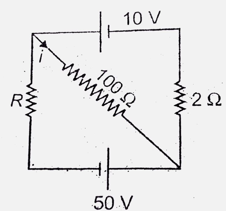
View SolutionIn the circuit shown, the current I will be zero when R is
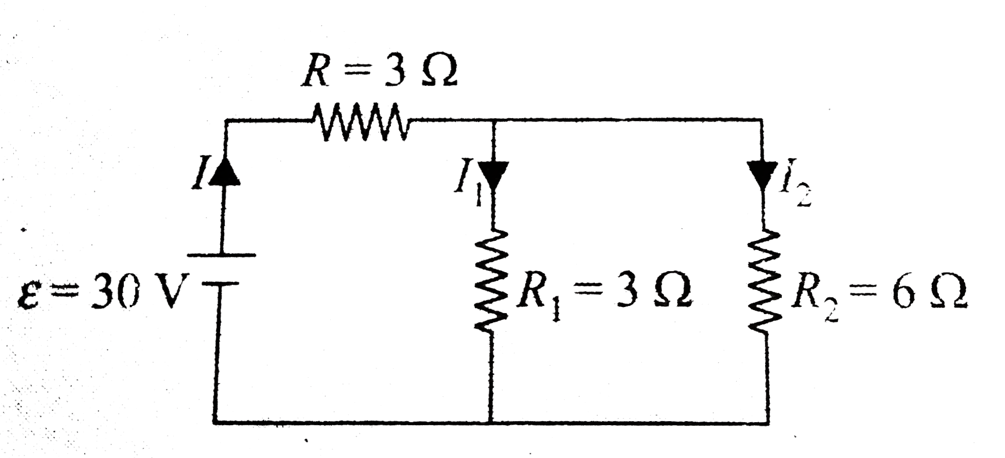
View SolutionIn the circuit given, find the currents I, I, and I2 in the circuit. (br)
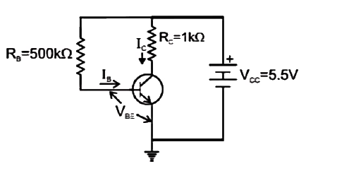
View SolutionIn the circuit shown in figure,the base current IB is 10μA and the collector current is 5.2 mA . The voltage (VBE) across the base and emitter is
View SolutionE1andE2 are two batteries having emfs of 3V and 4V and internal resistances of 2Ω and 1Ω respectively. They are connected as shown in Figure 2. Using Kirchhoff.s Laws of electrical circuits, calculate the current I1andI2.
View Solution
