A small signal voltage V(t)=V0sinωt is applied across an ideal capacitor C:
over a full cycle the capacitor C does not consume any energy from the voltage source.
current I(t) is in phase with voltage V(t)
current I(t) leads voltage V(t) by 180∘
current I(t), lags voltage V(t) by 90∘.
The correct Answer is:A
To solve the problem, we need to analyze the behavior of a small signal voltage applied across an ideal capacitor. The voltage is given by:
V(t)=V0sin(ωt)
Step 1: Understand the relationship between voltage and current in a capacitor
For an ideal capacitor, the current I(t) is related to the voltage V(t) by the following equation:
I(t)=CdV(t)dt
where C is the capacitance of the capacitor.
Step 2: Differentiate the voltage function
Now, we need to differentiate the voltage function V(t):
V(t)=V0sin(ωt)
Taking the derivative with respect to time t:
dV(t)dt=V0ωcos(ωt)
Step 3: Substitute the derivative into the current equation
Now we can substitute this derivative back into the equation for current:
I(t)=CdV(t)dt=C⋅V0ωcos(ωt)
Step 4: Express the current in terms of sine function
We can express the cosine function in terms of sine:
I(t)=C⋅V0ωcos(ωt)=C⋅V0ωsin(ωt+π2)
This shows that the current leads the voltage by π2 radians (or 90 degrees).
Step 5: Analyze the power consumed by the capacitor
The average power P consumed by the capacitor over a full cycle can be calculated using the formula:
P=1T∫T0V(t)I(t)dt
However, since the current leads the voltage by π2, the average power over a full cycle is zero:
P=VrmsIrmscos(ϕ)
where ϕ=π2. Since cos(π2)=0:
P=0
Conclusion
Thus, the capacitor does not consume any energy from the voltage source over a full cycle.
Final Answer
The current through the capacitor is given by:
I(t)=CV0ωcos(ωt)
And the average power consumed by the capacitor is zero.
---
For an ideal capacitor, the current I(t) is related to the voltage V(t) by the following equation:
Now, we need to differentiate the voltage function V(t):
Now we can substitute this derivative back into the equation for current:
We can express the cosine function in terms of sine:
The average power P consumed by the capacitor over a full cycle can be calculated using the formula:
Thus, the capacitor does not consume any energy from the voltage source over a full cycle.
The current through the capacitor is given by:
Similar Questions
Explain the term 'capacitive reactance'.Show graphically the variation of capacitive reactance with frequency of the applied alternating voltage.
An a.c. voltage E=E0sinωt is applied a across a pure capacitor C.Show mathematically that the current flowing through it leads the applied voltage by a phase angle of π/2
View SolutionExplain the term 'inductive reactance'.Show graphically the variation of inductive reactance with frequency of the applied alternating voltage.
An a.c. voltage E=E0sinωt is applied across a pure inductor L.Show mathematically that the current flowing through it lags behind the applied voltage by a phase angle of π/2.
View Solution
Knowledge Check
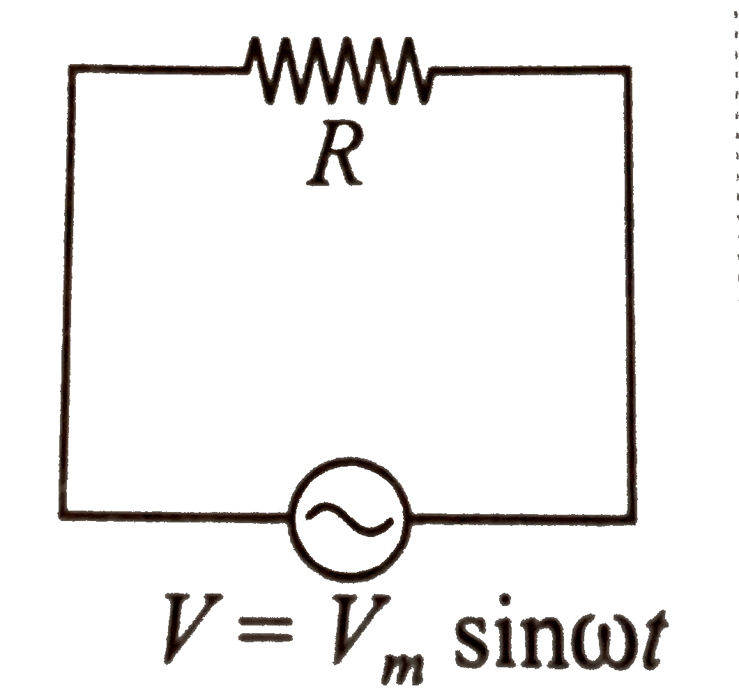
An ac source of voltage V=Vmsinωt is connected across the resistance R as shown in figure. The phase relation between current and voltage for this circuit is
 Aboth are in phaseBboth are out of phase by 90∘Cboth are out of phase by 120∘Dboth are out of phase by 180∘
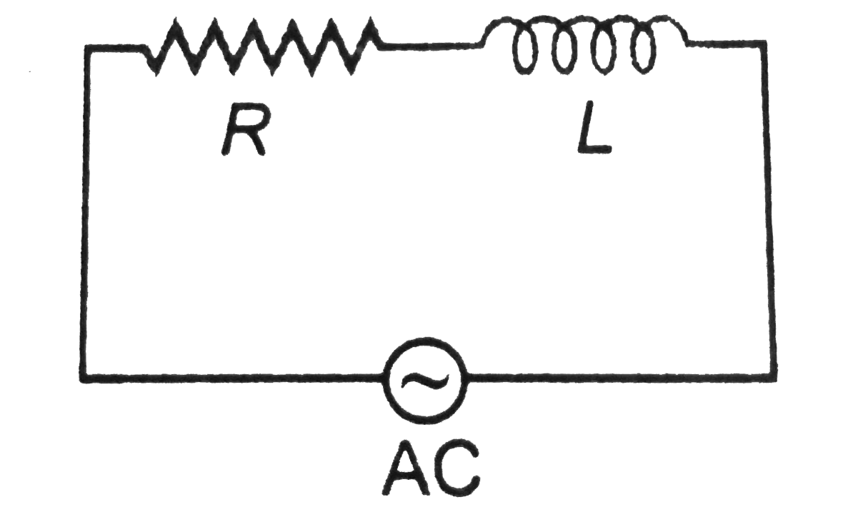
A circuit contains resistance R and an inductance L in series. An alternating voltage V=V0sinωt is applied across it. The currents in R and L respectively will be
 .
.
View SolutionA circuit contains resistance R and an inductance L in series. An alternating voltage V=V0sinωt is applied across it. The currents in R and L respectively will be
 .
.
View SolutionWhen a voltage V=V0 cos ωt is applied across a resistor of resistance R, the average power dissipated per cycle in the resistor is given by
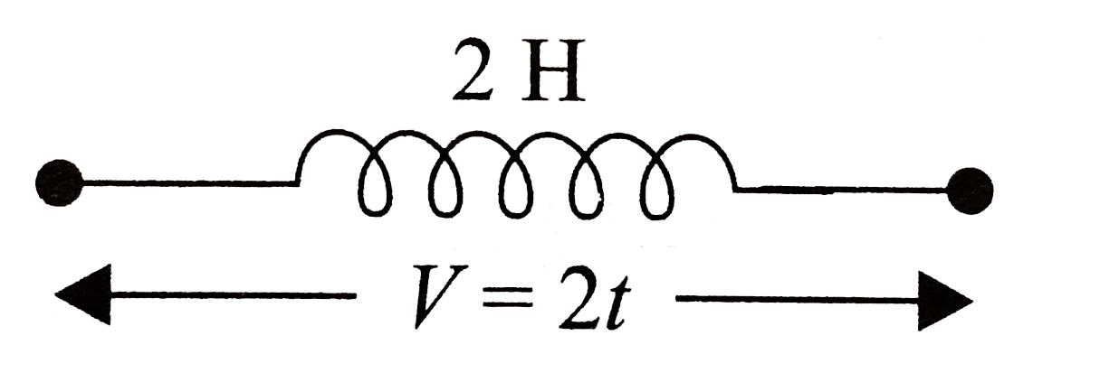
View SolutionA time varying voltage V= 2t (Volt) is applied across and ideal inductor of inductance L =2H as shown in Fig. Then (assume current to be zero at t =0)

View SolutionAn alternating potential V = Vosinωt is applied across a circuit. As a result the current,
I = Iosin(ωt−π2) flows in it. The power consecutive in the circuit per cycle is
View SolutionAn alternating voltage given as, V=100√2sin100t V is applied to a capacitor of 1μF. The current reading of the ammeter will be equal to ................ mA.
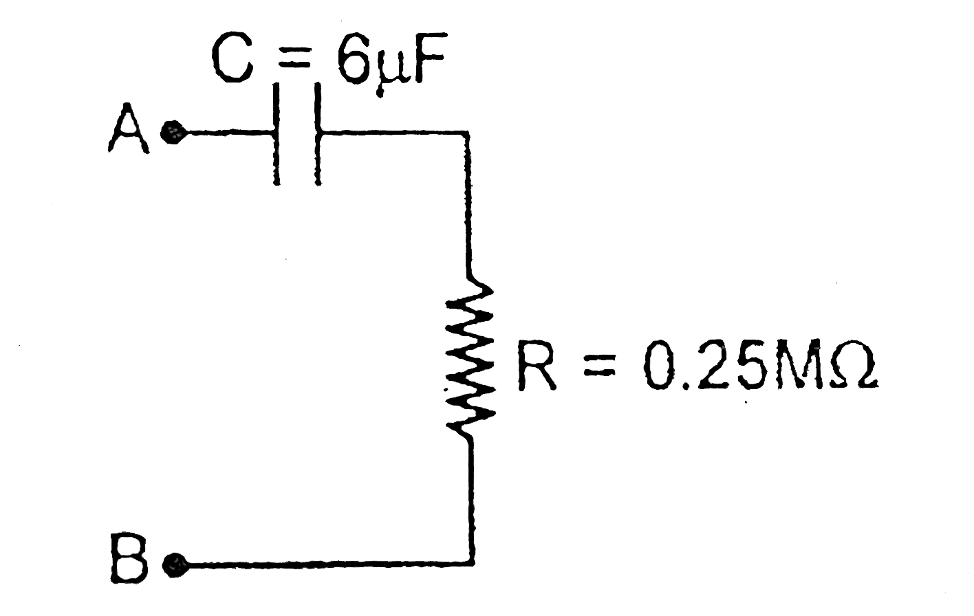
View SolutionA time varying voltage is applied across A & B such that voltage across capacitor is given by VC=2sin2t. What is maximum potential difference across the reistance?

View Solution
