Indicate the positions of load L, effort E and fulcrum F in the forearm shown alongsind in figure. Name the class of leverl.
 .
.
Step by step video & image solution for Indicate the positions of load L, effort E and fulcrum F in the forearm shown alongsind in figure. Name the class of leverl. . by Physics experts to help you in doubts & scoring excellent marks in Class 10 exams.
Updated on:21/07/2023Topper's Solved these Questions
- MACHINESBOOK - ICSECHAPTER - MACHINESEXERCISE - EXERCISE-3(A) MULTIPLE CHOICE TYPE
5 Videos
- MACHINESBOOK - ICSECHAPTER - MACHINESEXERCISE - EXERCISE-3(A) NUMERICALS
12 Videos
- MACHINESBOOK - ICSECHAPTER - MACHINESEXERCISE - EXERCISE-3(B) NUMERICALS
11 Videos
- HOUSEHOLD CIRCUITS BOOK - ICSECHAPTER - HOUSEHOLD CIRCUITS EXERCISE - EXERCISE -9(B) (MULTIPLE CHOICE TYPE)
2 Videos
- QUESTION PAPER 2022 TERM 1BOOK - ICSECHAPTER - QUESTION PAPER 2022 TERM 1EXERCISE - MULTIPLE CHOICE QUESTIONS
40 Videos
Similar Questions
State the class of levers and the relative positions of load (L), effort (E) and fulcrum (F) in each of the following cases.
(1) A bottle opener
(2) Sugar tongs.
View SolutionFigure, shows a lemon crushes,
(a) In the diagram, mark the position of the fulcrum F and the line of action of load L and effort E.

(b) Name the class of lever.
View SolutionState the class of levers and the relative positions of load (L), effort (E) and fulcrum (F) in (a) a bottle opener, and (b0 sugar tongs.
View SolutionDraw a simple diagram ofa fire tongs and mark on it the fulcrum F and the points of application of load L and effort E. (a) Name the class of lever. (b) if load arm is 15 cm and effort arm is 5 cm. what is its mechanical adavantage?
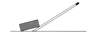
View SolutionThe diagram below shows a rod lifting a stone.
(a) Mark position of fulcrum F and draw arrows to show the directions of load L and effort E. (b) What class of lever is the rod ? (c) Give one more example of the same class of lever stated in part (b).
 .
.
View Solution
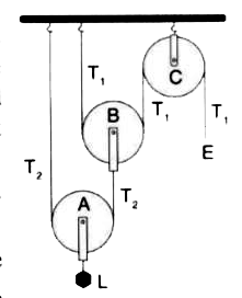
The diagram alongside shows an arrangement of three pulleys A,B and C. the load is marked as L and the effort as E.
(a) Name the pulleys A,B and C.
(b) Mark in the diagram the directions of load (L), effort (E) and tension T1andT2 in the two strings.
(c) How are the magnitudes of L and E related to the tension T1 ?
(d) Calculate mechanical advantage and velocity ratio of the arrangement.
(e) What assumptions have you made in parts (c) and (d) ?
View Solution
Put the relevant labels - load, fulcrum , and effort on each figure.
View SolutionMagnitude of slope i.e. steepness of graph shown in figure
l
View SolutionYou are given four pulleys and three strings. Draw a neat and labelled diagram to use them so as to obtain a maximum mechanical advantage equal to 8. In your diagram mark the directions of load L, effort E and tension in each strand.
What assumptions have you made to Obtain the required mechanical advantage ?
View SolutionIn Figure, draw a tackle to lift the load by applying the force in downward direction.
(a) Mark in the diagram the direction of load L and effort E.
(b) If the load is raised by 1 m, through what distance will the effot move ?
(c) State the number of strands of tackle supporting the load.
(d) What is the mechanical advantage of the system?

View Solution