Figure below shows the circuit of an electronic device :
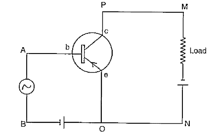
(i) Which electronic device : a rectifier, an amplifier or an oscillator does the above circuit represent?
(ii) State where the input voltage is applied and 1 where the output voltage is available.
(iii) Compare the output voltage of this circuit with its input voltage.
The circuit diagram represents an amplifier.
(ii) Input is applied between AB and output is available across load resistance.
(iii) The output voltage is amplified and is 180∘ out of phase with its input voltage.
Similar Questions
Knowledge Check
- Question 1 - Select One
In the circuit shown in figure, when the input voltage of the base resistance is 10 V, Vbe is zero and Vce is also zero. Then
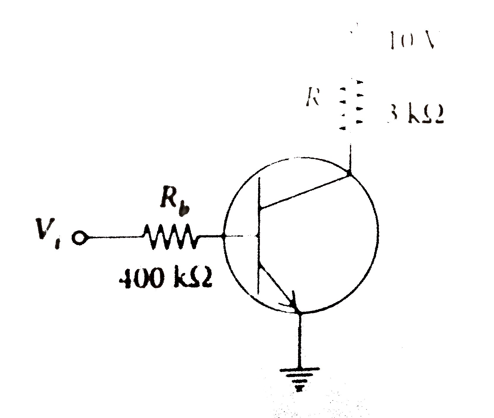 Aβ=110BIb=25μACIc=3.33mADboth (A) and (C )
 - Question 2 - Select One
A transistor has a current amplification factor (current gain) of 50. In a common emitter amplifier circuit, the collector resistance is chosen as 5Ω and the input resistance is 1Ω. The output voltage if input voltage is 0.01 V is
A-2 VB−5VC-2.5 VD-1 V
In a common emitter amplifier circuit using an n-p-n transistor, the phase difference between the input and the output voltages will be:-
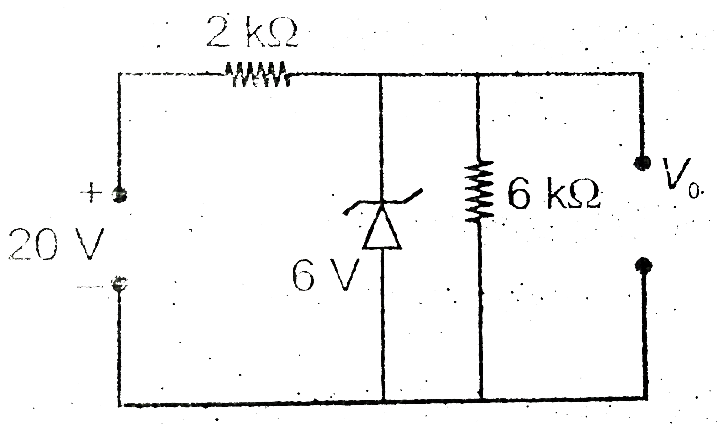
View SolutionTake the breakdown voltage of the zener diode used in the given circuit as 6V. For the input voltage shown in figure below , the time variation of the output voltage is : (Graphs drawn are schematic and not to scale )
 View Solution
A common emitter circuit is used as an amplifier, its current gain is 50. if input resistance is 1kΩ and input voltage is 5 volt then output current will be
View SolutionIn a common emitter amplifier , the load resistance of the output circuit is 500 times the resistance of the input circuit. If α=0.98 , then find the voltage gain and power gain .
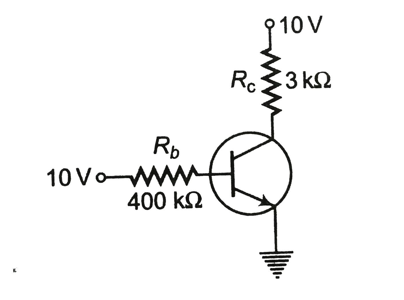
View SolutionIn the circuit shown in figure when the input voltage of the base resistance is 10 V . Find the values of Ib,Icandβ .
 View Solution
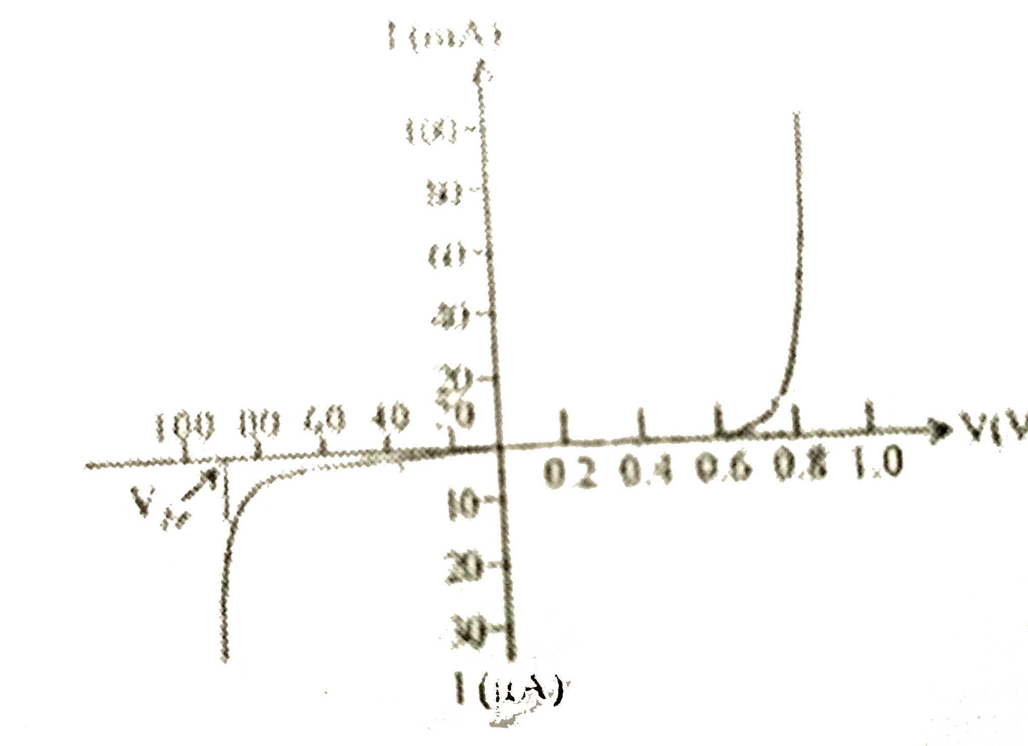
The figure below shows the V-I characteristic of a semiconductor diode.
(i ) Identify the semiconductor diode used.
(ii) Draw the circuit diagram to obtain the given characteristic of this device.
(ii) Briefly explain how this diode can be used as a voltage regulator.
 View Solution


