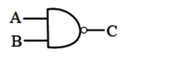
Draw a diagram to show how NAND gates can be combined to obtain an OR gate. (Truth table is not required).
To combine NAND gates to obtain an OR gate, we can follow these steps:
1. Understand the NAND Gate Functionality:
- A NAND gate outputs a low signal (0) only when all of its inputs are high (1). In all other cases, it outputs a high signal (1).
- The truth table for a NAND gate is as follows:
- Input (A, B) → Output
- (0, 0) → 1
- (0, 1) → 1
- (1, 0) → 1
- (1, 1) → 0
2. Use Two NAND Gates to Create NOT Gates:
- Connect the input A to the first NAND gate. Since a NAND gate can be used to create a NOT gate, connect both inputs of the first NAND gate to A.
- The output of this NAND gate will be NOT A (A').
- Similarly, connect the input B to the second NAND gate. Connect both inputs of this second NAND gate to B.
- The output of this NAND gate will be NOT B (B').
3. Combine the Outputs of the Two NOT Gates:
- Now, take the outputs from the two NAND gates (which are A' and B') and connect them as inputs to a third NAND gate.
- This third NAND gate will output the result of the expression (A' AND B')', which is equivalent to A OR B (A + B).
4. Final Diagram:
- Draw the first NAND gate with inputs A and A, and label the output as A'.
- Draw the second NAND gate with inputs B and B, and label the output as B'.
- Draw the third NAND gate with inputs A' and B', and label the output as A + B (which is the OR operation).
Diagram Representation:
A−−−−|⊢−−A'|NAND|A−−−−||B−−−−|⊢−−B'|NAND|B−−−−||A'−−−−|||NAND⊢−−A+BB'−−−−|∣
- A NAND gate outputs a low signal (0) only when all of its inputs are high (1). In all other cases, it outputs a high signal (1).
- The truth table for a NAND gate is as follows:
- Input (A, B) → Output
- (0, 0) → 1
- (0, 1) → 1
- (1, 0) → 1
- (1, 1) → 0
- Connect the input A to the first NAND gate. Since a NAND gate can be used to create a NOT gate, connect both inputs of the first NAND gate to A.
- The output of this NAND gate will be NOT A (A').
- The output of this NAND gate will be NOT B (B').
- Now, take the outputs from the two NAND gates (which are A' and B') and connect them as inputs to a third NAND gate.
- This third NAND gate will output the result of the expression (A' AND B')', which is equivalent to A OR B (A + B).
- Draw the first NAND gate with inputs A and A, and label the output as A'.
- Draw the second NAND gate with inputs B and B, and label the output as B'.
- Draw the third NAND gate with inputs A' and B', and label the output as A + B (which is the OR operation).
A−−−−|⊢−−A'|NAND|A−−−−||B−−−−|⊢−−B'|NAND|B−−−−||A'−−−−|||NAND⊢−−A+BB'−−−−|∣
Similar Questions
NAND gate is-
View SolutionShow with the help of a diagram, how you will obtain an AND gate using only NAND gates, (Truth table is not required)
View SolutionFor given logic gate truth table is
 View Solution
How many minimum NAND gate are required to obtain NOR gate :-
View SolutionWhat is the symbol of a NOR gate? Write its truth table.
View SolutionDraw the symbol for AND gate and write its truth table.
 View Solution
How many NAND gates used to form AND gate.
View SolutionGive the logic symbol of NAND gate.
View SolutionThe minimum NOR gates are required to make one NAND gate are
View SolutionWhat is a NAND gate ? Write its truth table.
View Solution

