The four capacitors, each of 25μF are connected as shown in figure. The DC voltmeter reads 200V. The charge on each plate of capacitor is
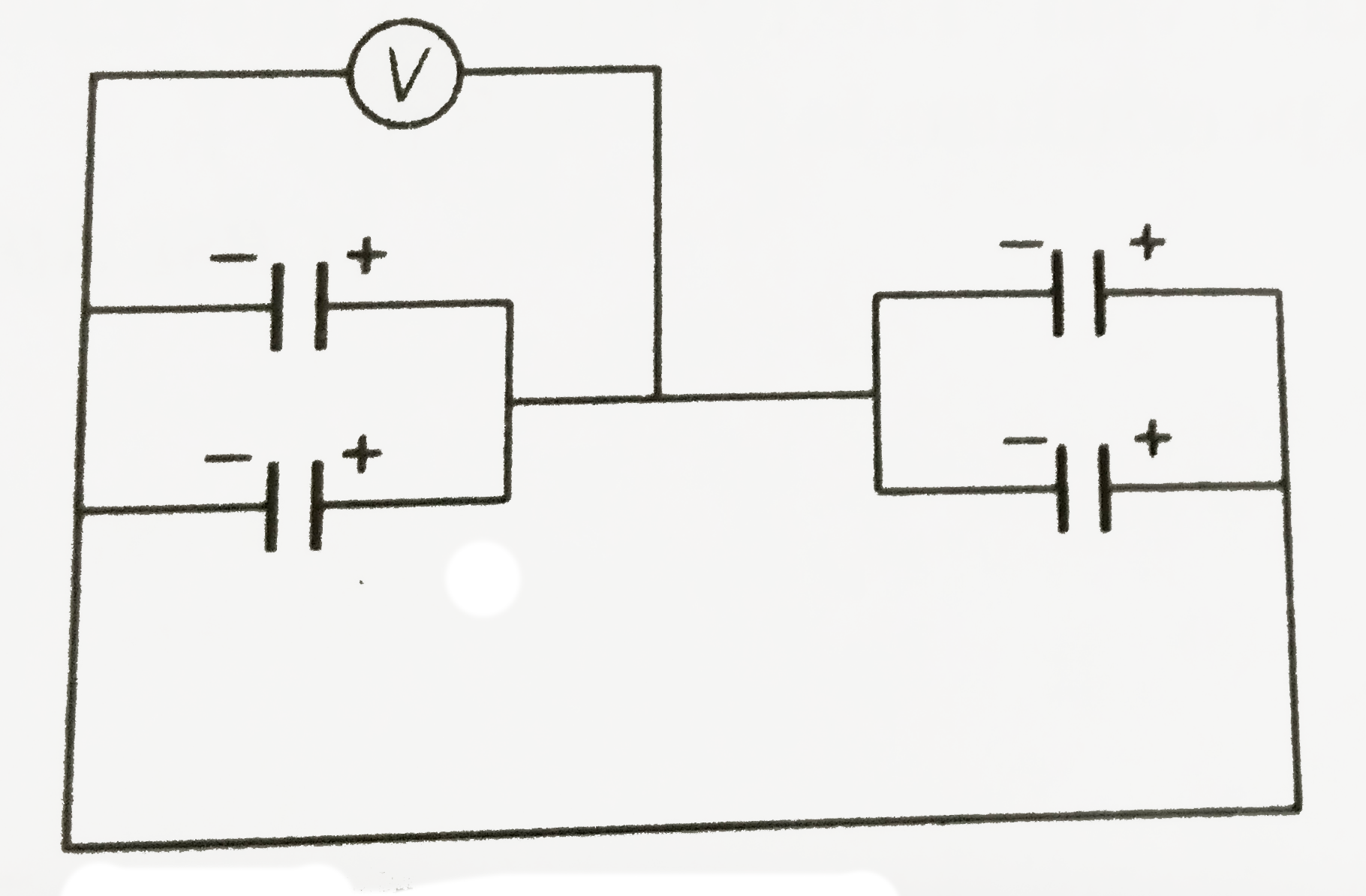
±2×10⁻³C
±5×10⁻³C
±2×10⁻²C
±5×10⁻²C
The correct Answer is:B
Step by step video & image solution for The four capacitors, each of 25 muF are connected as shown in figure. The DC voltmeter reads 200V. The charge on each plate of capacitor is by Physics experts to help you in doubts & scoring excellent marks in Class 12 exams.
Updated on:21/07/2023Similar Questions
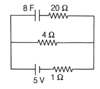
A capacitor of 8 F is connected as shown in the figure. At steady state Charge on the plates of the capacitor
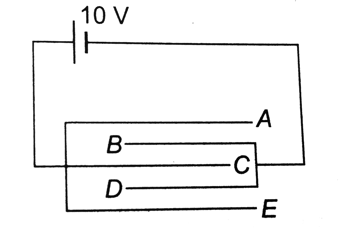
View SolutionFive identical capacitor plates are arranged such that they make four capacitors each of 2μF. The plates are connected to a source of emf 10V. The charge on plate C is
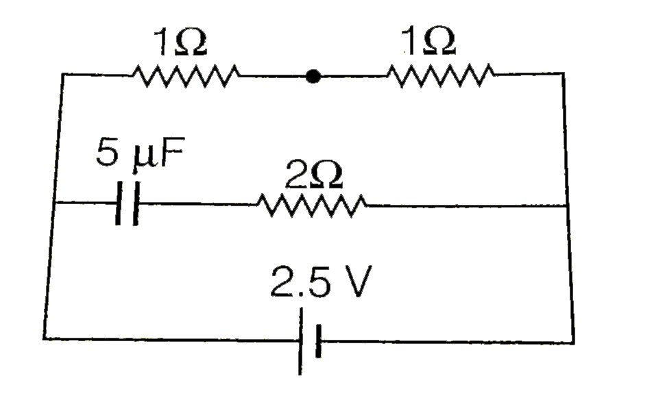
View SolutionA capacitor of capacitaance 5μF is connected as shown in the figure.The internal resistane of the cell is 0.5ω The amount of charge on the cap[acitor plates is
View SolutionA capacitor of capacitaance 5μF is connected as shown in the figure.The internal resistane of the cvell is 0.5ω The amount of charge on the cap[acitor plates is

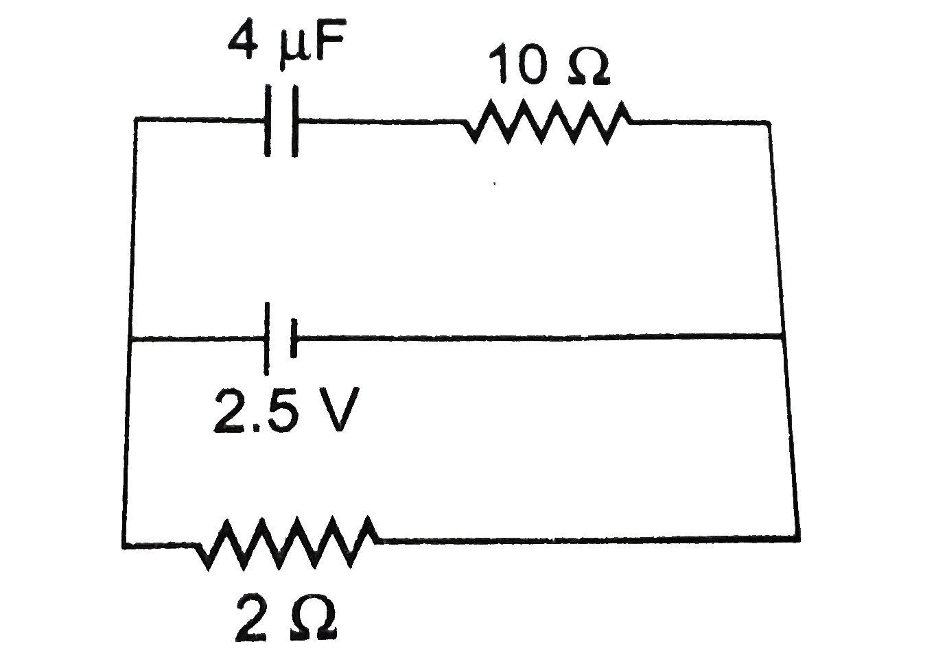
View SolutionA capacitor of 4μF is connected as shwon in the figure. The internal resistance of the battery is 0.5Ω. The amount of charge on the capacitor plates will be
View SolutionSix equal capacitors each of capacitance 10μF are connect as shown in the figure. Then the equivalent capacitance between A and B is
View SolutionRows of capacitors 1,2,4,8…..∞ capacitors, each of capacitance 2μF, are connected in parallel as shown in figure. The potential difference across AB = 10 V, then

View SolutionFour capacitors each of capacity 8μF area connected with each other as shown in figure. The equivalent capacitance between points X and Y will be

View SolutionA network of four capacitors each of 15μF capacitance is connected to a 500 V supply as shown in the figure . Determine (a) equivalent capacitance of the network and (b) charge on each capacitor .
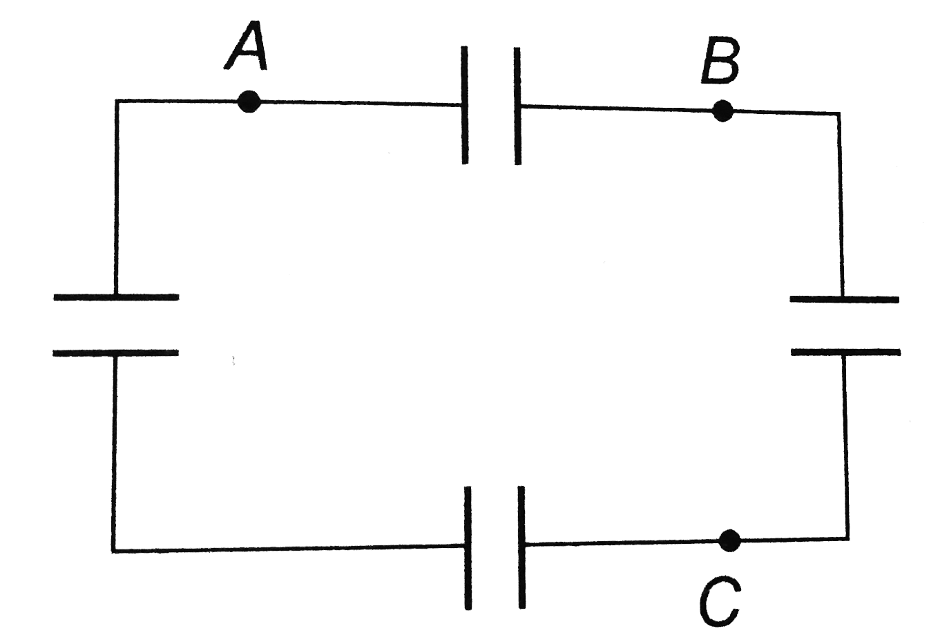
View SolutionFour capacitors of each of capacity 3μF are connected as shown in the adjoining figure. The ratio of equivalent capacitance between A and B and between A and C will be
View Solution

