In, given C1=3μF,C2=5μF,C3=9μF, and C4=13μF. What is the potential differnce between points A and B?
 .
.
13V
9V
0V
11V
The correct Answer is:A
22V get will divide into series combination of C3 and C4.
Topper's Solved these Questions
- BOOK - CENGAGE PHYSICS ENGLISHCHAPTER - CAPACITOR AND CAPACITANCEEXERCISE - Multile Correct11videos
CAPACITOR AND CAPACITANCE
- BOOK - CENGAGE PHYSICS ENGLISHCHAPTER - CAPACITOR AND CAPACITANCEEXERCISE - Comprhension35videos
CAPACITOR AND CAPACITANCE
- BOOK - CENGAGE PHYSICS ENGLISHCHAPTER - CAPACITOR AND CAPACITANCEEXERCISE - Subjective24videos
CAPACITOR AND CAPACITANCE
- BOOK - CENGAGE PHYSICS ENGLISHCHAPTER - ATOMIC PHYSICSEXERCISE - ddp.4.315videos
ATOMIC PHYSICS
- BOOK - CENGAGE PHYSICS ENGLISHCHAPTER - CENGAGE PHYSICS DPPEXERCISE - subjective type51videos
CENGAGE PHYSICS DPP
Similar Questions
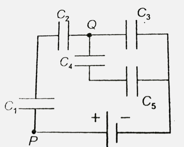
In the circuit shown C1=15μF,C2==30μF,C3=30μF,C4=30μF and C5=60μF. At steady state, the potential difference between points P and Q is 50 V. Calculate the potential difference across capacitor with capacitance C5
 View Solution
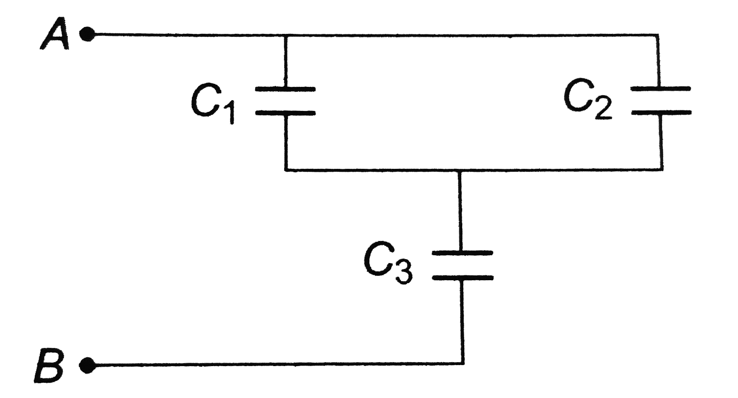
In the given network capacitance, C1=10μF,C2=5μF and C3=4μF. What is the resultant capacitance between A and B?
 View Solution
In the given network capacitance, C1=10μF,C2=5μF and C3=4μF. What is the resultant capacitance between A and B?
 View Solution
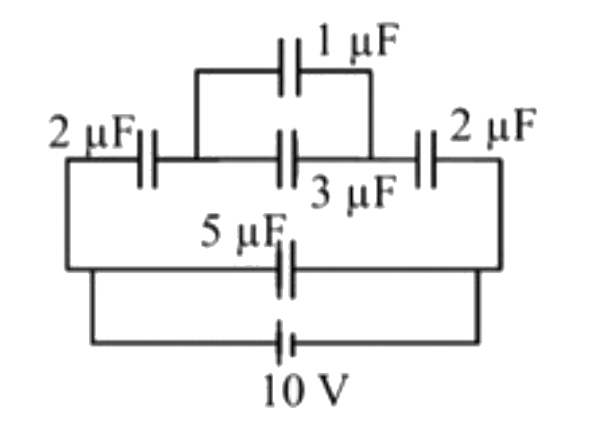
The ratio of potential differences between 1μFand5μF capacitors is
 View Solution
In the accompanying diagram , if C1=3μF,C2=6μF,C3=9μF,C4=12μF,C5=15μFandC6=18μF , then the equivalent capacitor between the ends A and B is
 View Solution
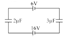
What is the potential difference across 2μF capacitor in the circuit shown?
 View Solution
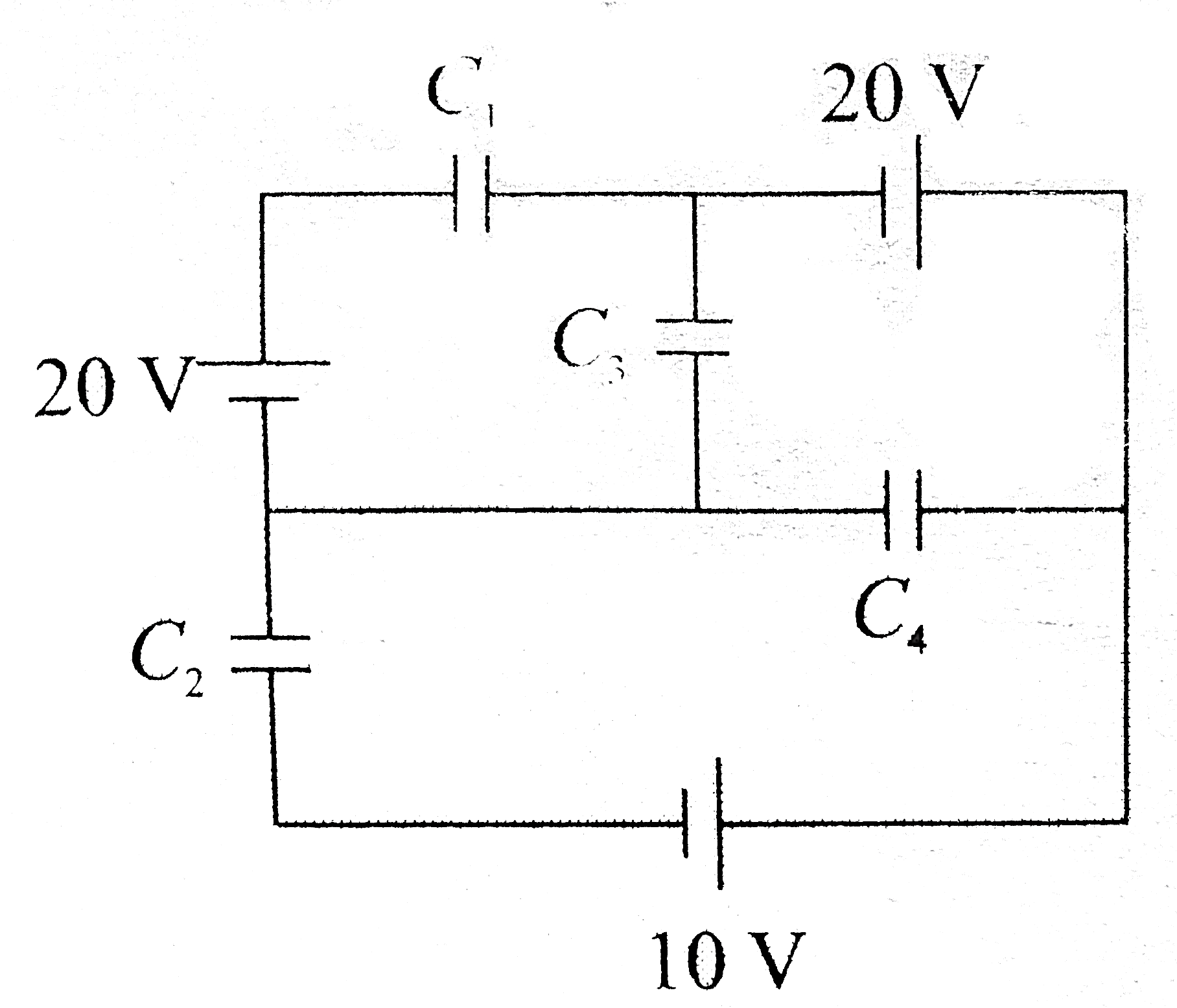
Four capacitors C1=8μF,
C2=2μf,C3=6μF, and C4=6,μF are arranged as shown in. Find the charge on all the capacitors in the circuit.
 .View Solution
A potential of V=3000V is applied to a combination of four initially uncharged capacitors as shown in the figure. Capacitors A, B, C and D have capacitances CA=6.0μF,CB=5.2μF,CC=1.5μFandCD=3.8μF, respectiely. If the battery is disconnected, then potential difference across capacitor B is (approximately)
 View Solution
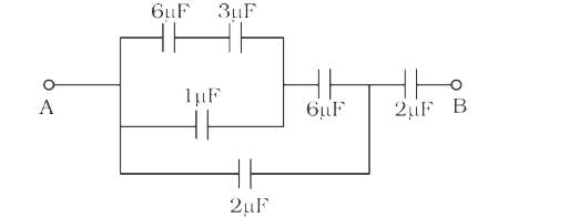
In the diagram shown, the net capacitance between the points A and B is (in μF)
 View Solution
For section AB of a circuit shown in , C1=1μF,C2=2μF,E=10V, and the potential difference VA−VB=−10V. Charge on capacitor C1 is
 . View Solution

