For section AB of a circuit shown in , C1=1μF,C2=2μF,E=10V, and the potential difference VA−VB=−10V. Charge on capacitor C1 is
 .
.
0μC
20/3μC
40/3μC
none of these
The correct Answer is:C
VA−qC1−EqC2=VB or VA−VB−E=Q(1C1+1C2)
or q=−403μC .
Topper's Solved these Questions
- CAPACITOR AND CAPACITANCEBOOK - CENGAGE PHYSICS ENGLISHCHAPTER - CAPACITOR AND CAPACITANCEEXERCISE - Multile Correct
11 Videos
- CAPACITOR AND CAPACITANCEBOOK - CENGAGE PHYSICS ENGLISHCHAPTER - CAPACITOR AND CAPACITANCEEXERCISE - Comprhension
35 Videos
- CAPACITOR AND CAPACITANCEBOOK - CENGAGE PHYSICS ENGLISHCHAPTER - CAPACITOR AND CAPACITANCEEXERCISE - Subjective
24 Videos
- ATOMIC PHYSICSBOOK - CENGAGE PHYSICS ENGLISHCHAPTER - ATOMIC PHYSICSEXERCISE - ddp.4.3
15 Videos
- CENGAGE PHYSICS DPPBOOK - CENGAGE PHYSICS ENGLISHCHAPTER - CENGAGE PHYSICS DPPEXERCISE - subjective type
51 Videos
Similar Questions
A circuit has section AB as shown in figure. The emf of the source equals E=10V, the capacitor capacitances are equal to C1=1.0μF and C2=2.0μF, and the potential difference VA−VB=5.0V. Find the voltage across each capacitor.

View SolutionIn the circuit shown in figure

E1=10V,E2=4V,r1=r2=1Ω and R=2Ω.
Find the potential difference across battery 1 and battery 2.
View SolutionIn the circuit shown in figure

E1=10V,E2=4V,r1=r2=1Ω and R=2Ω.
Find the potential difference across battery 1 and battery 2.
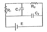
View SolutionIn the circuit shown in figure, R(1)=1Ω,R2=2Ω,C1=1μF,C2=2μF and E=6V. Calculate charge on each capacitor in steady state
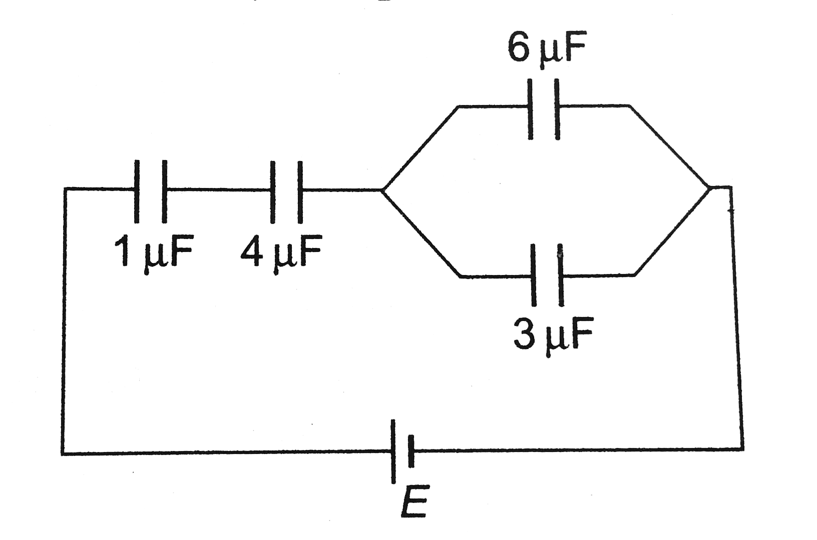
View Solutiongiven that potential differene across 1μF capacitor is 10V. Then,
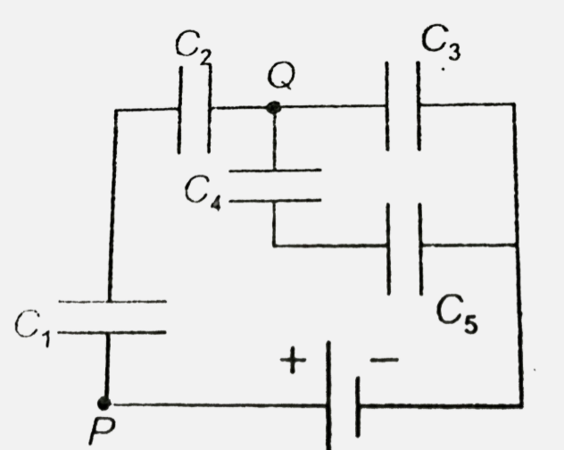
View SolutionIn the circuit shown C1=15μF,C2==30μF,C3=30μF,C4=30μF and C5=60μF. At steady state, the potential difference between points P and Q is 50 V. Calculate the potential difference across capacitor with capacitance C5
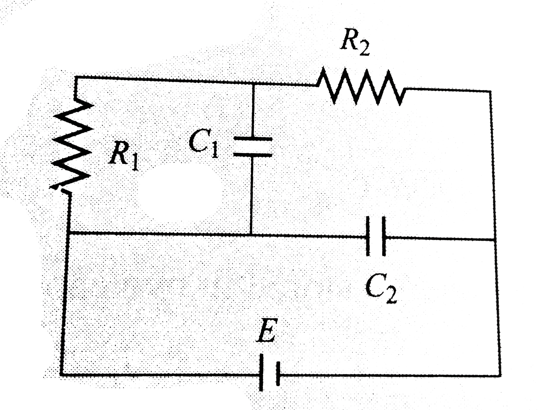
View SolutionIn the circuit shown in fig. R1=10Ω,R2=5Ω,C1=1μF,C2=2μF, and E =6V. Calculate the charge on each capactor in the stedy state.
View SolutionThree capacitors C1=6μF,C2=12μF and C3=20μF are connected to a 100 V battery, as shown in figure below:
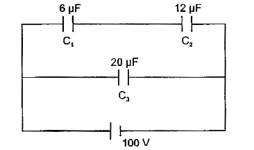
(i) Charge on each plate of capacitor C1.
(ii) Electrostatic potential energy stored in capacitor C3.
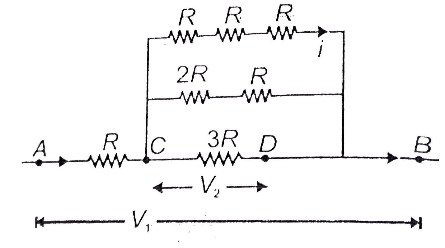
View SolutionIn the circuit shown, the potential differences, V1 ( between A and B ) and V2 ( between C and D ), are
View SolutionThe arrangement shows a part of complete circuit. The potentials at point A and B are V1 and V2 respectively . Find the potential at point P.

Strategy : The two capacitors C1 and C2 are connected in series . Therefore the charge on both of the capacitors is same . Let the potential at P is V .
View Solution
