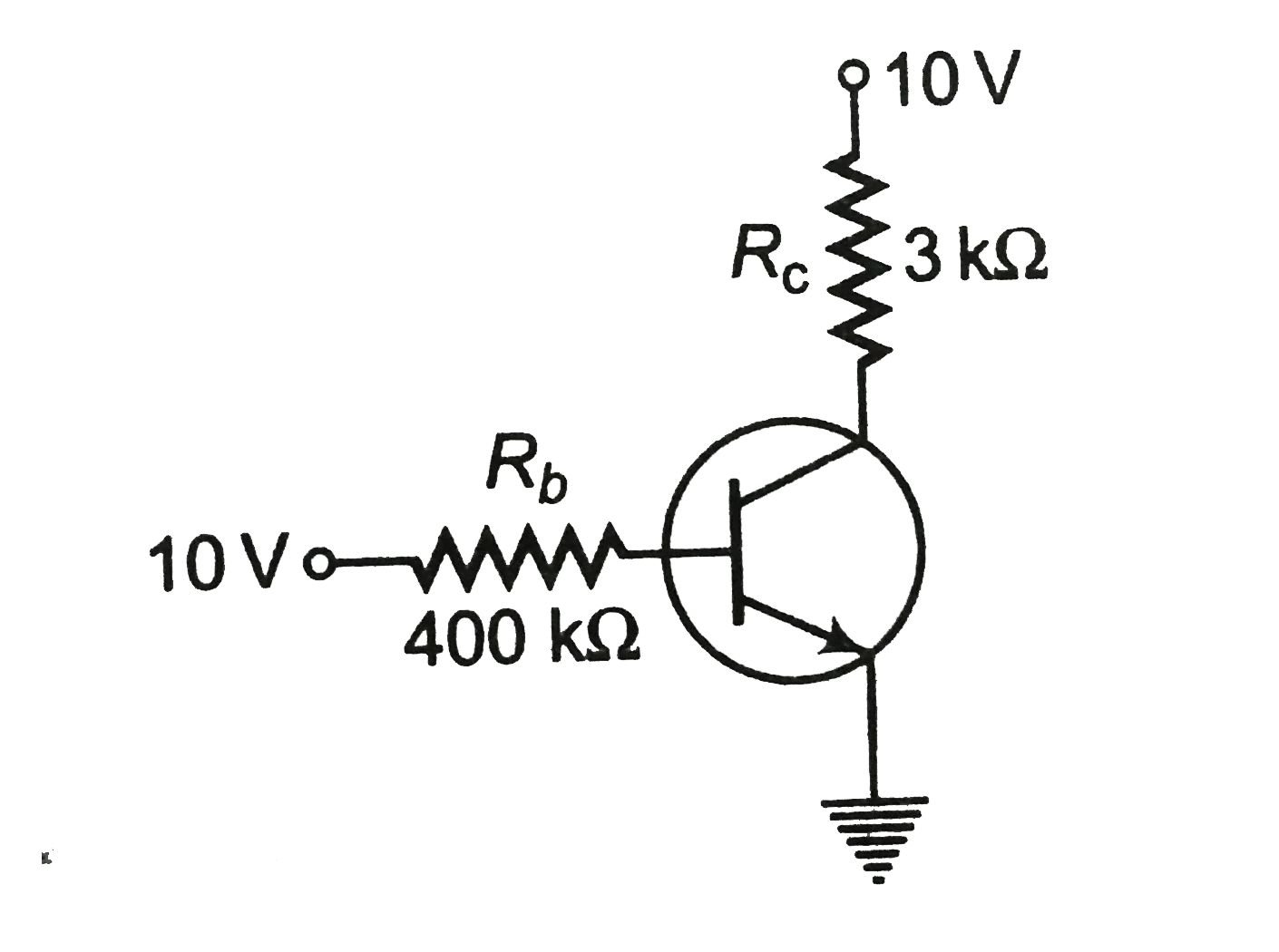
In the circuit shown in Fig. when the input voltage of the base resistance is 10V,Vbe is zero and Vce is also zero. Find the values of I,I and β.
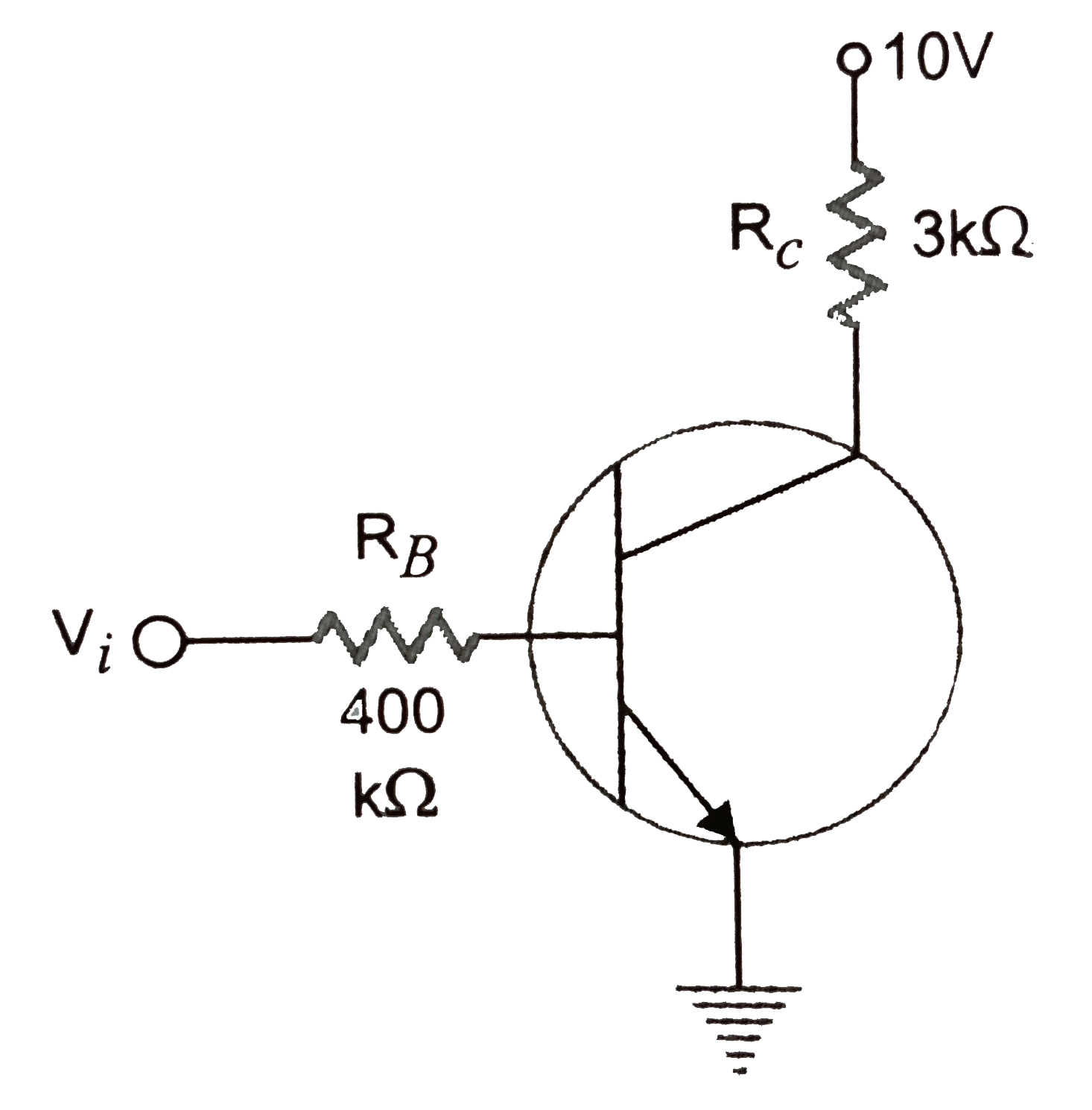
Given, woltage across RB=10V
Resistance RB=400kΩ
VBE=VCE=0RC=3kΩ
IB=Voltage across RBRB
=10400×103=25×10−6A=25μA
Voltage across RC=10V
=3.33×10⁻³A=3.33mA
β=ICIB=3.33×10−325×10−6
=1.33×102=133
Topper's Solved these Questions
- BOOK - NCERT EXEMPLAR ENGLISHCHAPTER - NUCLEIEXERCISE - Very short Anwer type question14videos
NUCLEI
- BOOK - NCERT EXEMPLAR ENGLISHCHAPTER - MOVING CHARNGES AND MAGNETISMEXERCISE - Long Answer Type Questions7videos
MOVING CHARNGES AND MAGNETISM
- BOOK - NCERT EXEMPLAR ENGLISHCHAPTER - RAY OPTICS AND OPTICAL INSTRUMENTS EXERCISE - VERY SHORT ANSWER TYPE QUESTIONS16videos
RAY OPTICS AND OPTICAL INSTRUMENTS
Similar Questions
Knowledge Check
- Question 1 - Select One
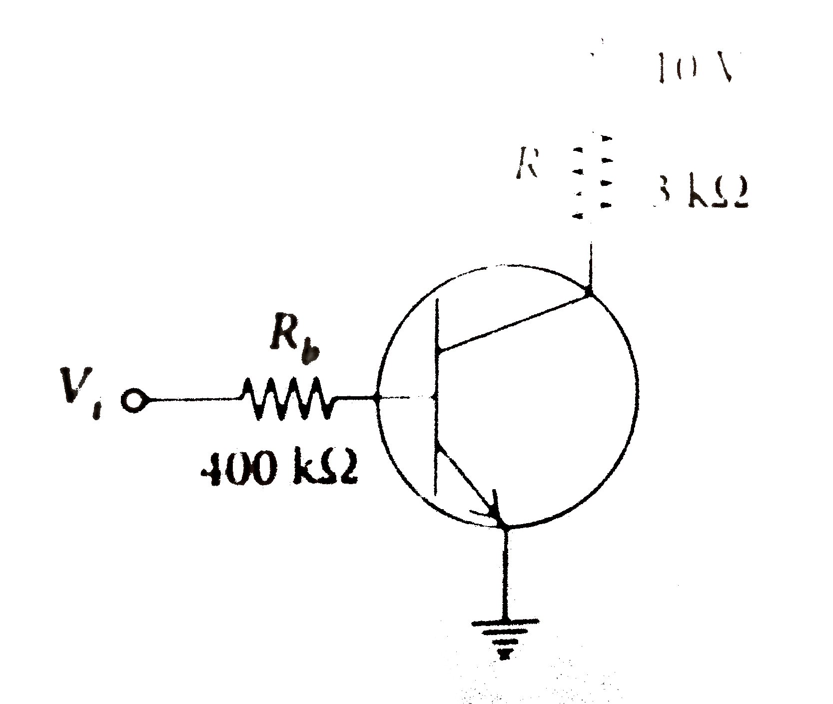
In the circuit shown in figure, when the input voltage of the base resistance is 10 V, Vbe is zero and Vce is also zero. Then
 Aβ=110BIb=25μACIc=3.33mADboth (A) and (C )
 - Question 2 - Select One
In the circuit shown in figure, the silicon and germanium diodes start conducting at 0.7 V and 0.3 V respectively. What are the values of V0 and I?
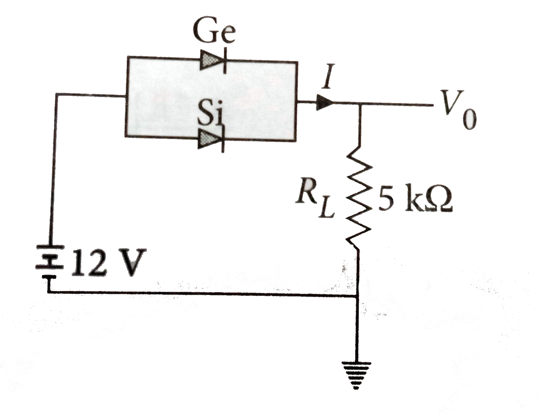 A12 V, 2.4 mAB11.7 V, 2.34 mAC11.3 V, 2.26 mAD11 V, 2.2 mA
In the circuit shown, the current I will be zero when R is
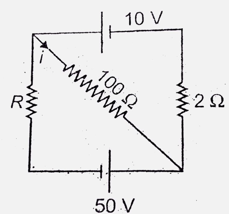 View Solution
Consider the circuit arrangnent shown in Fig. for studying input and output characteristics of npn transistor in CE configuration.
Select the values of R and R for a transistor whose VBE=0.7V, so that the transistor is operating at point Q as shown in the characteristics shown in Fig.
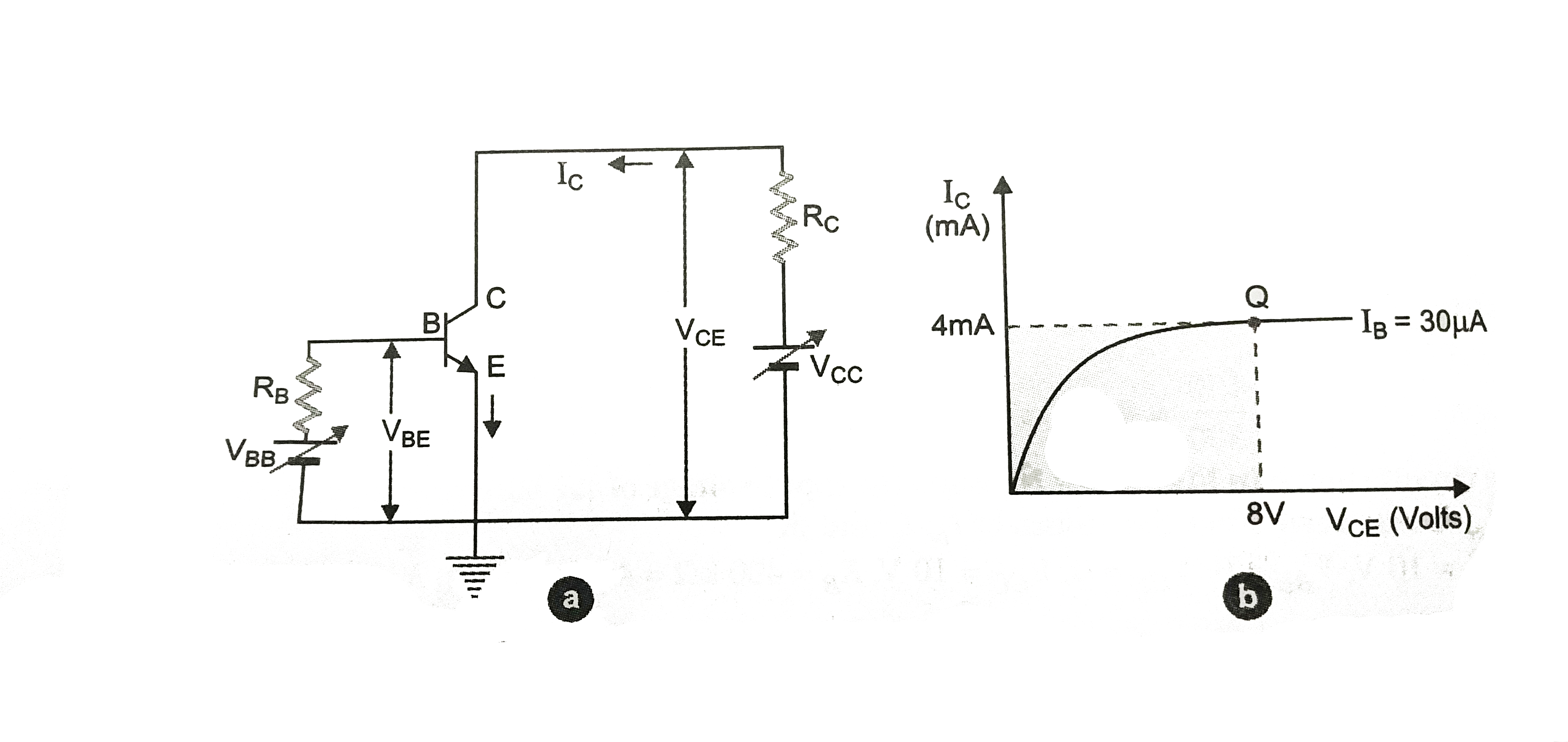 Given that the input impedance of the transistor is very small and VCC=VBB=16V, also find the voltage gain and power gain of circuit making appropriate assumptions.View Solution
In the circuit shown in figure potential differences across 6Ω resistance is 4 volt. Find V and i values across each resistance. Also find emf E of the applied battery.
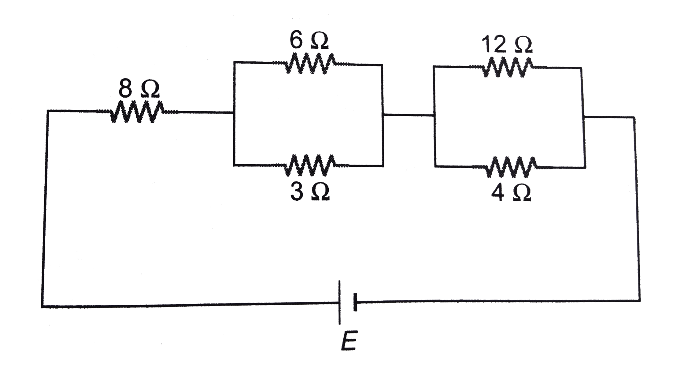 View Solution
For the circuit shown figure answer the following questions
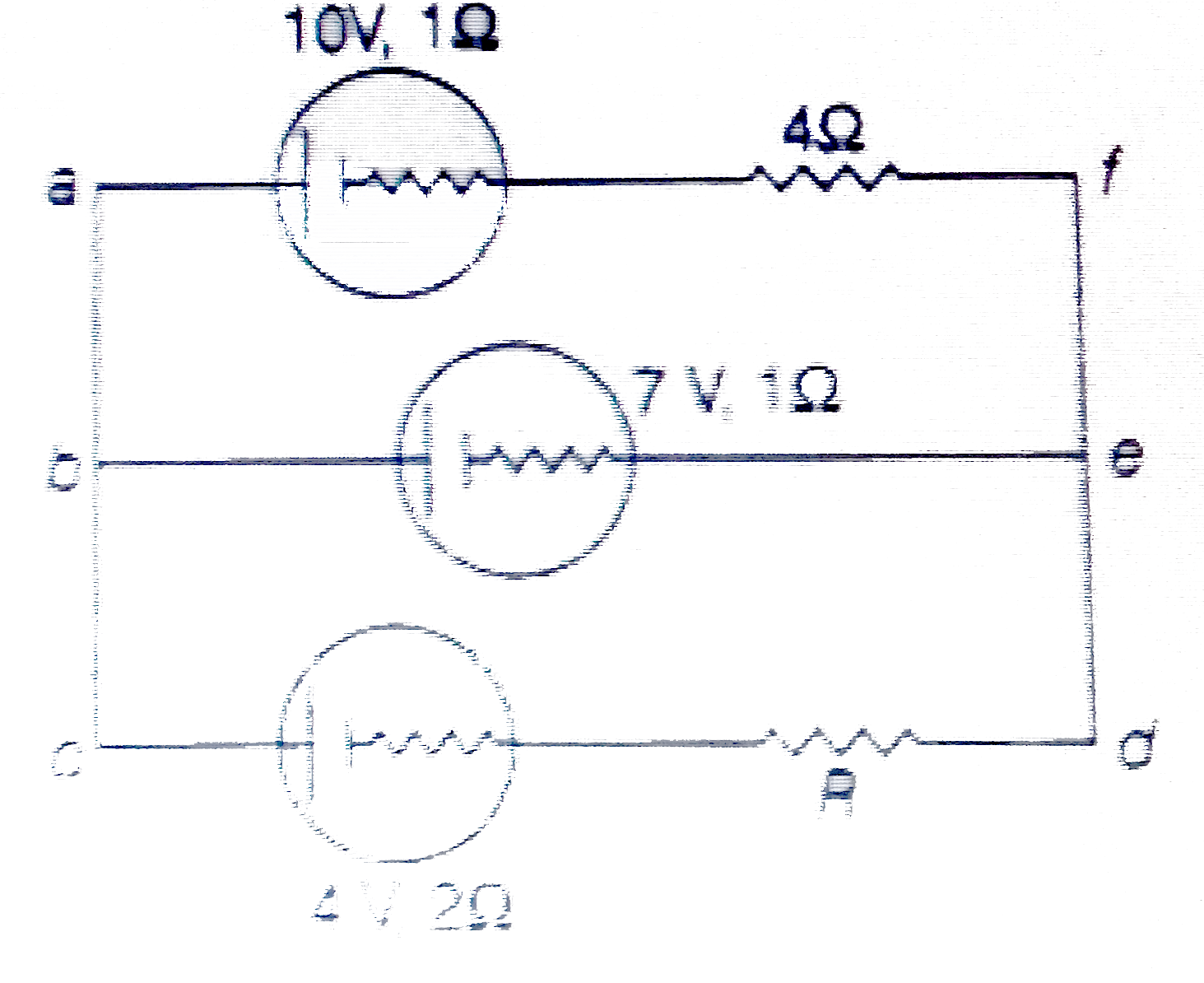
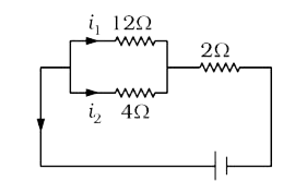
For what value of R, current through 7V battery is zero?View SolutionIn the circuit shown, the currents I1 and I2 are if the applied potential is of 12V,internal resistance 1 ohm:
 View Solution
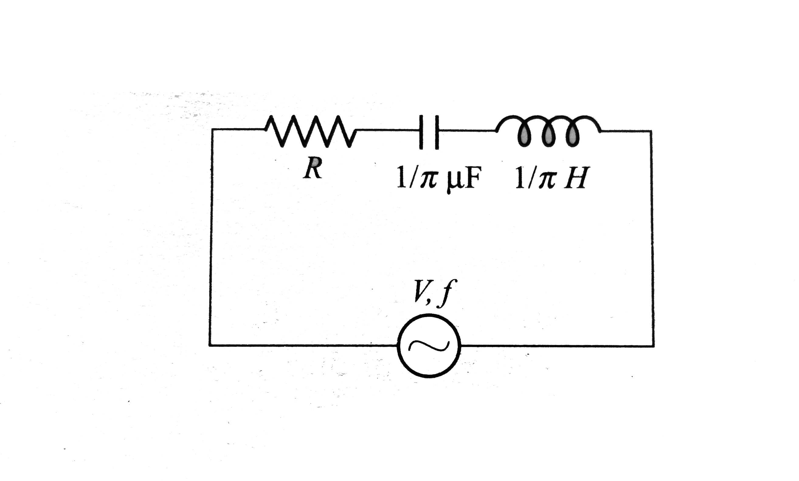
In an ac circuit shown in fig , the supply voltage has a constant rms value v but variable frequency f. At resonance, the circuit
 View Solution


