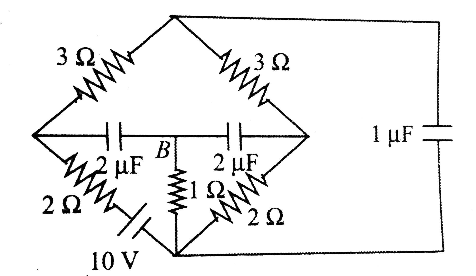
The circuit shown in fig 5.223 is in steady state.
find the charges on the capacitors C1andC2 respectively.
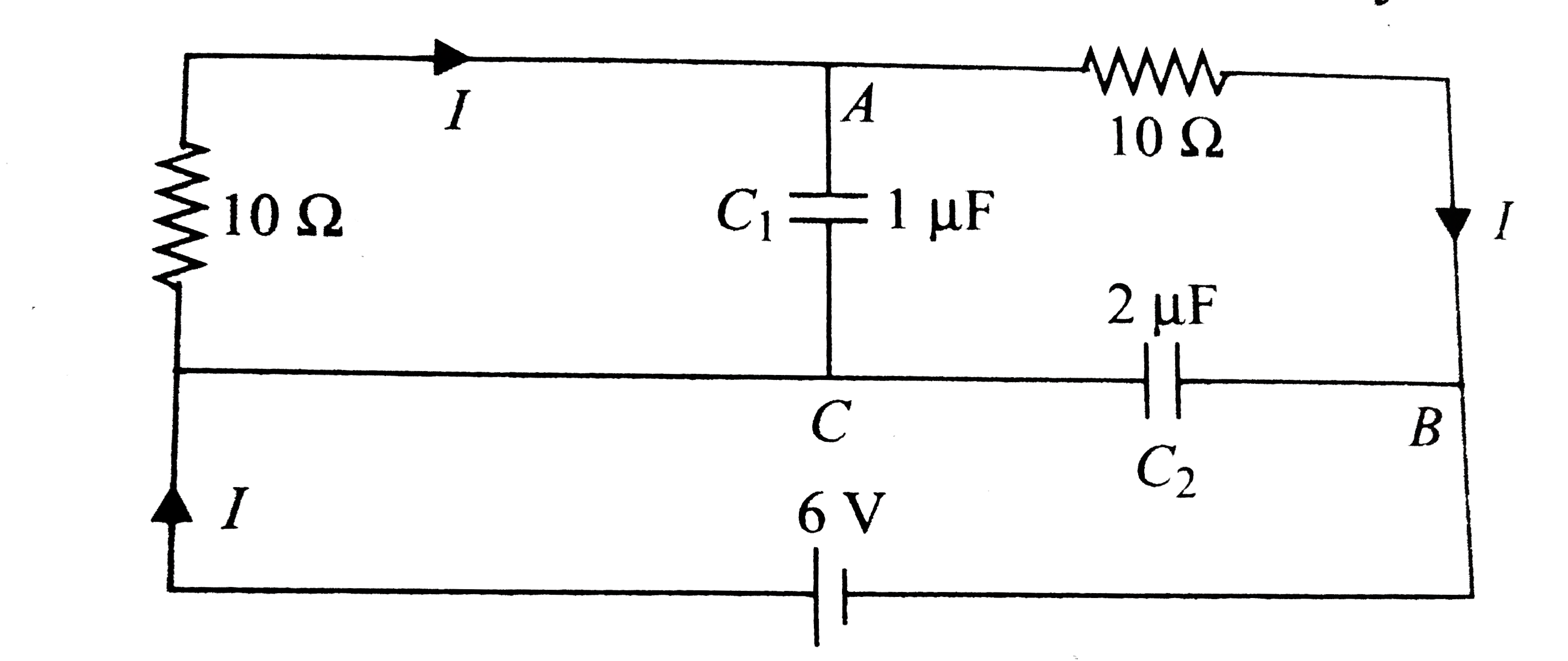
In steady state, current will flow as shown In fig
I=6(10+10)=0.30A
Potential difference across C1 is same as that across 10Ω on left
side. So

we can se that potential differecne across C2is6V. So charge
on C2isq2=2×6=12μC
Topper's Solved these Questions
- ELECTRIC CURRENT AND CIRCUITBOOK - CENGAGE PHYSICS ENGLISHCHAPTER - ELECTRIC CURRENT AND CIRCUITEXERCISE - Single Correct
72 Videos
- ELECTRIC CURRENT AND CIRCUITBOOK - CENGAGE PHYSICS ENGLISHCHAPTER - ELECTRIC CURRENT AND CIRCUITEXERCISE - Multiple Correct
16 Videos
- ELECTRIC CURRENT AND CIRCUITBOOK - CENGAGE PHYSICS ENGLISHCHAPTER - ELECTRIC CURRENT AND CIRCUITEXERCISE - Exercise 5.2
50 Videos
- ELECTRIC CURRENT & CIRCUITSBOOK - CENGAGE PHYSICS ENGLISHCHAPTER - ELECTRIC CURRENT & CIRCUITSEXERCISE - Kirchhoff s law and simple circuits
15 Videos
- ELECTRIC FLUX AND GAUSS LAWBOOK - CENGAGE PHYSICS ENGLISHCHAPTER - ELECTRIC FLUX AND GAUSS LAWEXERCISE - MCQ s
38 Videos
Similar Questions
In steady state, find the charge on 3μF capacitor in μC
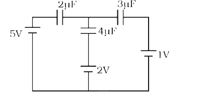
View SolutionIn the circuit shown in figure, find the steady state charges on oth the capacitors.
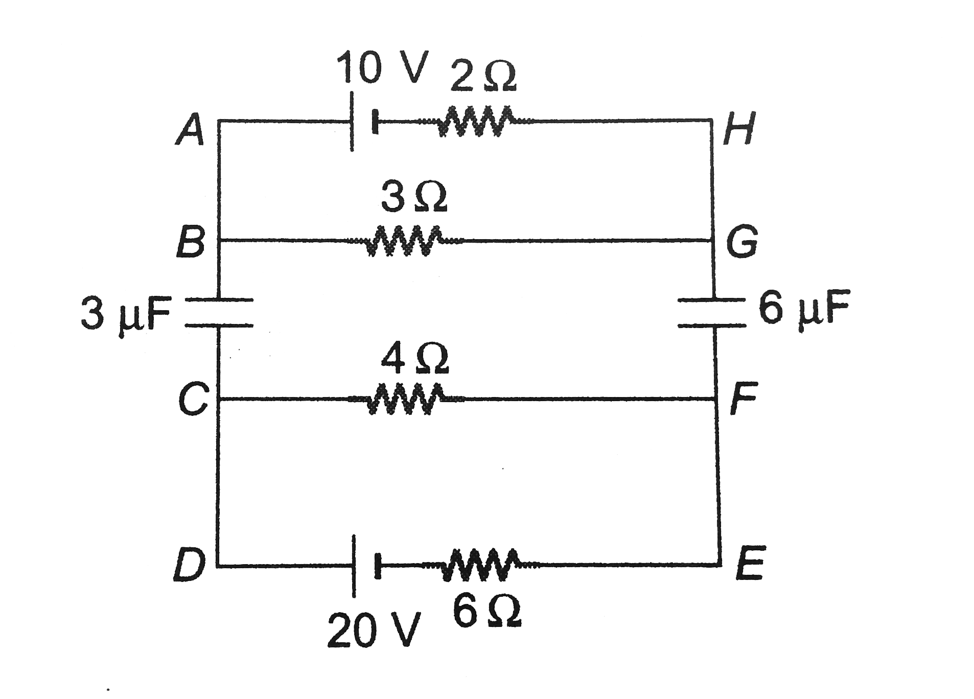
View SolutionIn the circuit shown in the figure, in steady state:
The charge on 5μF capacitor is
View SolutionThe circuit is in a steady state.
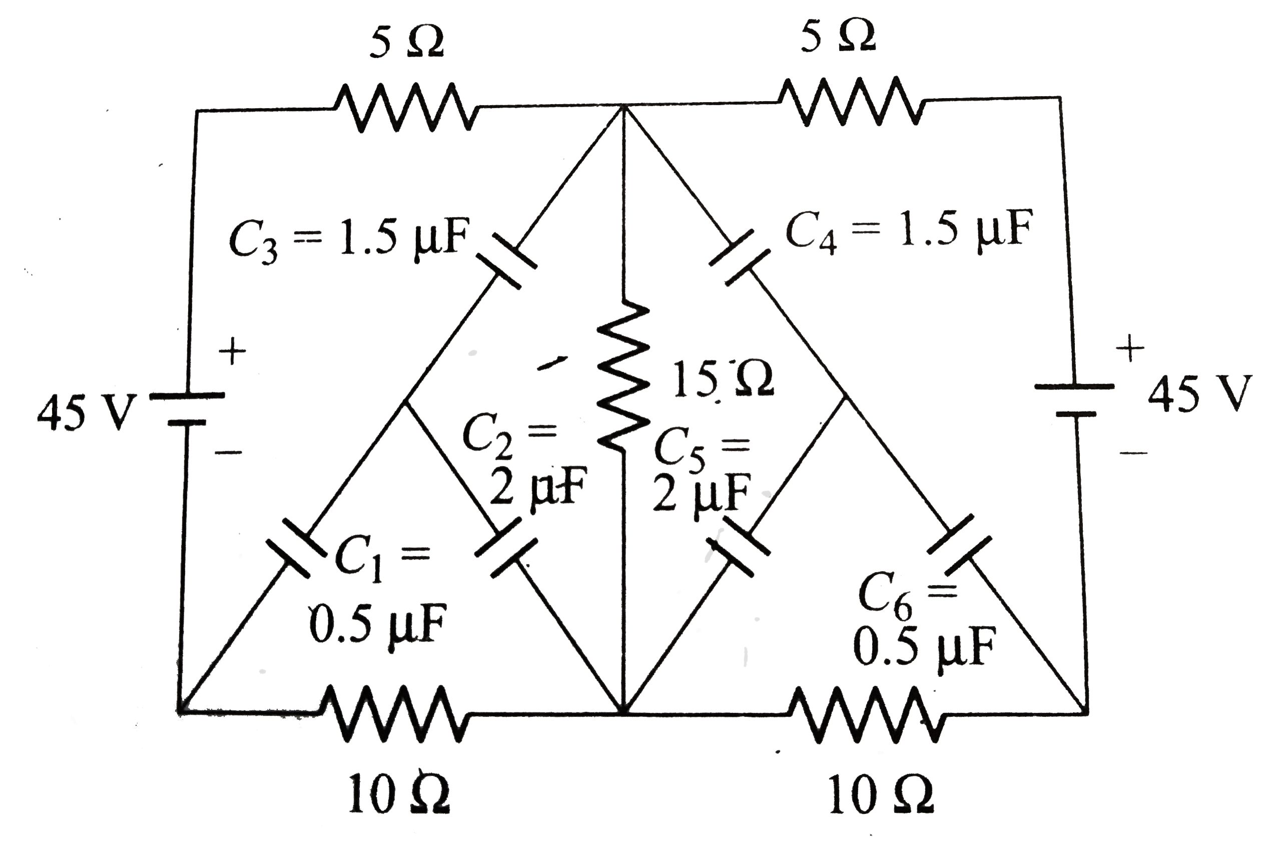
The charge in capacitor C1 is
View SolutionIn the circuit shown , the charges on the capacitors A and B are respectively
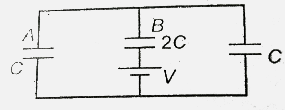
View SolutionThe capacitors shown in figure. Is in steady state. The energy stored in the capacitor is

View SolutionThe circuit is in a steady state.
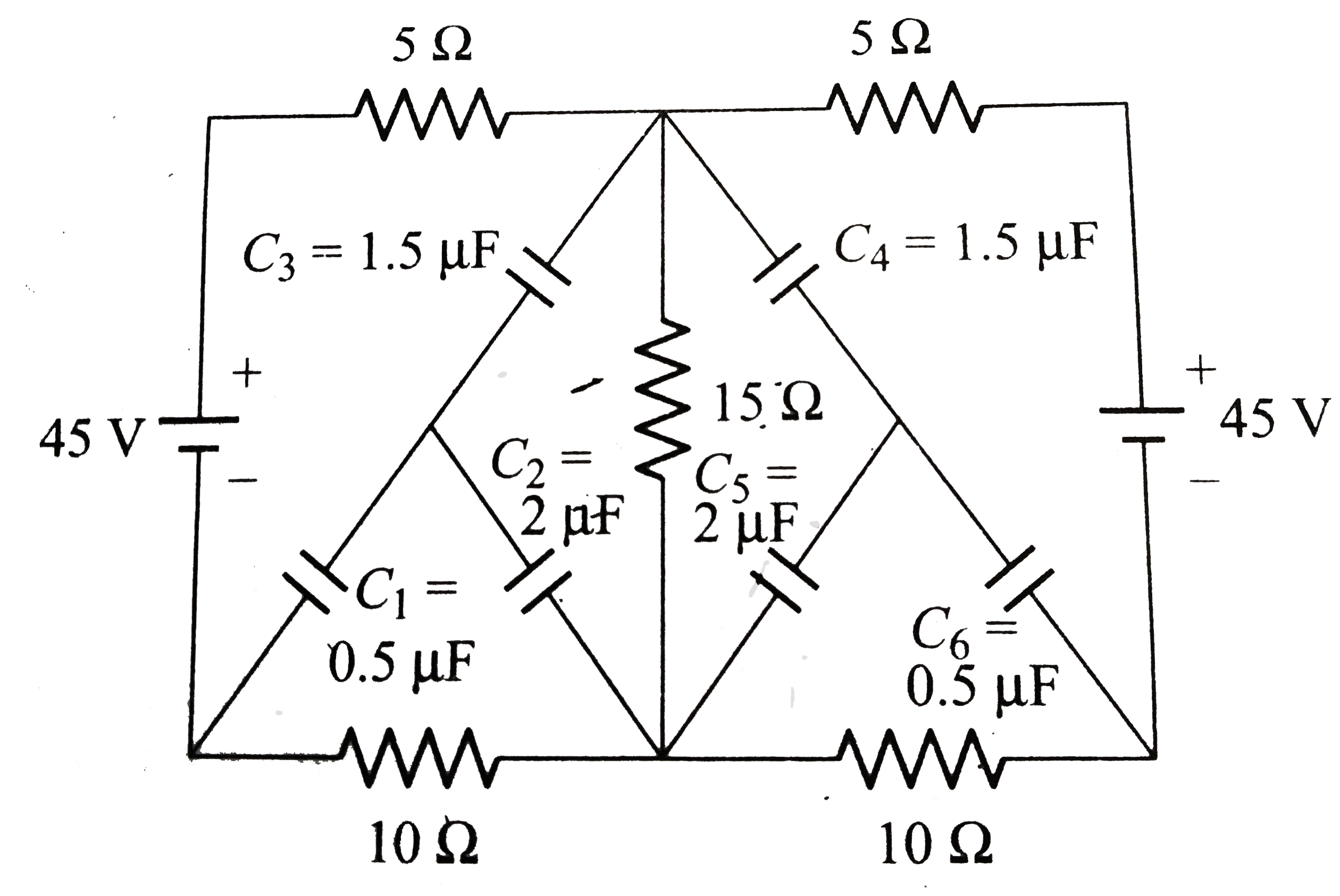
The charge in capacitor C2 is
View SolutionThe circuit is in a steady state.
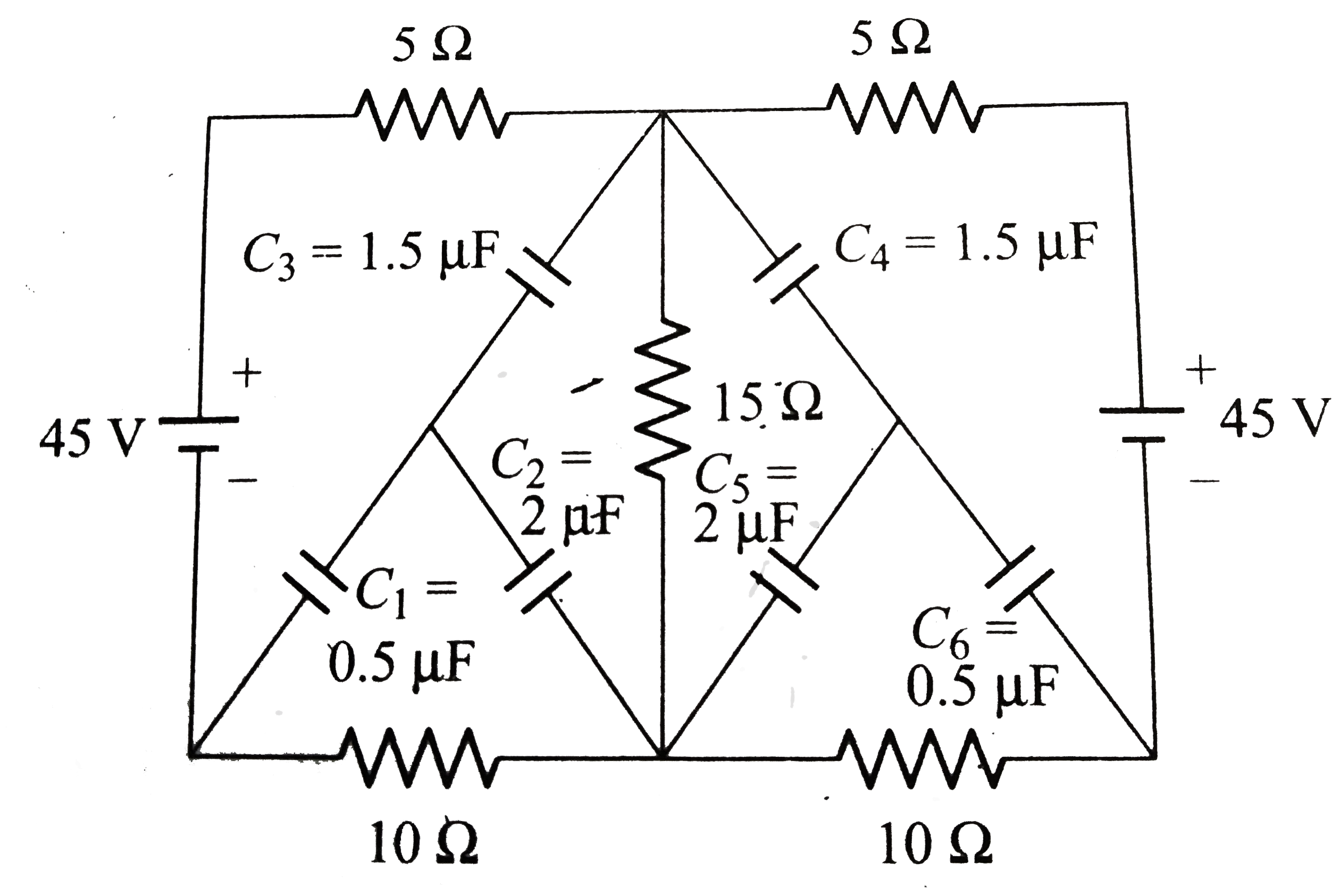
The charge in capacitor C3 is
View SolutionIn steady state, find the charge on the capacitor in (μC) shown in figure.
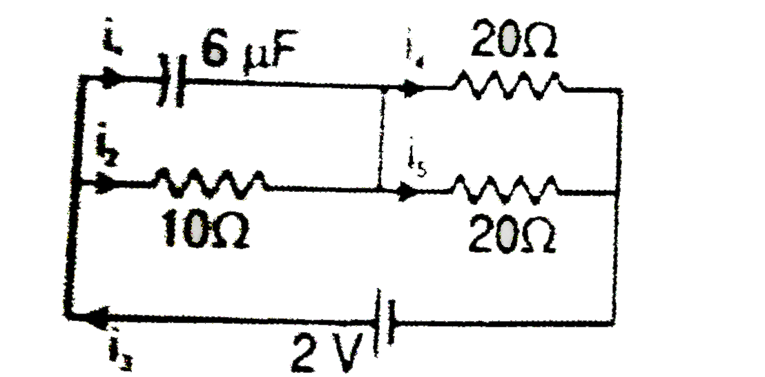
View SolutionThe circuit shown in fig. Is in steady state.
i. Find the energy stored in the capacitors shown in fig.
ii. Find the rate at which battery supplies energy.
View Solution