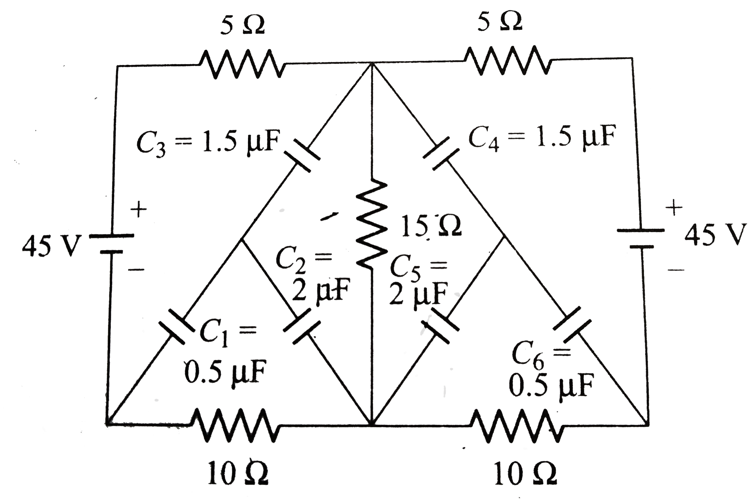
In the circuit shown in the figure, in steady state:
The charge on 5μF capacitor is
30μC
40μC
50μC
60μC
The correct Answer is:A
To find the charge on the 5 µF capacitor in the given circuit at steady state, we can follow these steps:
Step 1: Understand the Steady State Condition
In a steady state, the current flowing through the branches containing capacitors is zero. This means that the capacitors are fully charged and there is no further current flowing through them.
Hint: Remember that capacitors block DC current in steady state.
Step 2: Identify the Circuit Elements
We need to identify the resistances in the circuit and how they are connected. For this problem, we assume there are resistors connected in series.
Hint: Look for resistors that are connected in series and add their resistances.
Step 3: Calculate the Equivalent Resistance
If the resistors are connected in series, the total or equivalent resistance (R_eq) can be calculated by simply adding the individual resistances together. For example, if we have resistors of 4Ω, 2Ω, 2Ω, and 2Ω, the equivalent resistance is:
Req=4+2+2+2=10Ω
Hint: Use the formula for resistors in series: Req=R1+R2+R3+...
Step 4: Calculate the Current in the Circuit
Using Ohm's Law (V = IR), we can find the current (I) flowing through the circuit. If we assume a total voltage (V_total) is applied across the circuit, we can rearrange the formula to find I:
I=VtotalReq
Assuming a total voltage of 6V, we have:
I=6V10Ω=0.6A
Hint: Make sure to use the total voltage provided in the circuit.
Step 5: Determine the Voltage Across the Capacitor
To find the voltage (V) across the 5 µF capacitor, we need to consider the voltage drop across the resistors in series. If the voltage drop across the 4Ω resistor is:
V1=I×R1=0.6A×4Ω=2.4V
And for the 2Ω resistor:
V2=I×R2=0.6A×2Ω=1.2V
The total voltage across the capacitor is the sum of the voltage drops:
V=V1+V2=2.4V+1.2V=3.6V
Hint: Remember to sum the voltage drops across the resistors leading to the capacitor.
Step 6: Calculate the Charge on the Capacitor
Now that we have the voltage across the capacitor, we can use the formula for charge (Q) on a capacitor:
Q=C×V
Where:
- C = 5 µF = 5×10⁻⁶F
- V = 3.6 V
Substituting the values:
Q=5×10−6F×3.6V=18×10−6C=18µC
Hint: Use the formula Q=C×V and ensure the units are consistent.
Final Answer
The charge on the 5 µF capacitor is 18 µC.
In a steady state, the current flowing through the branches containing capacitors is zero. This means that the capacitors are fully charged and there is no further current flowing through them.
We need to identify the resistances in the circuit and how they are connected. For this problem, we assume there are resistors connected in series.
If the resistors are connected in series, the total or equivalent resistance (R_eq) can be calculated by simply adding the individual resistances together. For example, if we have resistors of 4Ω, 2Ω, 2Ω, and 2Ω, the equivalent resistance is:
Using Ohm's Law (V = IR), we can find the current (I) flowing through the circuit. If we assume a total voltage (V_total) is applied across the circuit, we can rearrange the formula to find I:
To find the voltage (V) across the 5 µF capacitor, we need to consider the voltage drop across the resistors in series. If the voltage drop across the 4Ω resistor is:
Now that we have the voltage across the capacitor, we can use the formula for charge (Q) on a capacitor:
- C = 5 µF = 5×10⁻⁶F
- V = 3.6 V
The charge on the 5 µF capacitor is 18 µC.
Topper's Solved these Questions
- ELECTROSTATICSBOOK - DC PANDEY ENGLISHCHAPTER - ELECTROSTATICSEXERCISE - Matrix Matching
2 Videos
- ELECTROSTATICSBOOK - DC PANDEY ENGLISHCHAPTER - ELECTROSTATICSEXERCISE - Integer
17 Videos
- ELECTROSTATICSBOOK - DC PANDEY ENGLISHCHAPTER - ELECTROSTATICSEXERCISE - JEE Advanced
44 Videos
- ELASTICITYBOOK - DC PANDEY ENGLISHCHAPTER - ELASTICITYEXERCISE - Medical entrances s gallery
21 Videos
- EXPERIMENTSBOOK - DC PANDEY ENGLISHCHAPTER - EXPERIMENTSEXERCISE - Subjective
15 Videos
Similar Questions
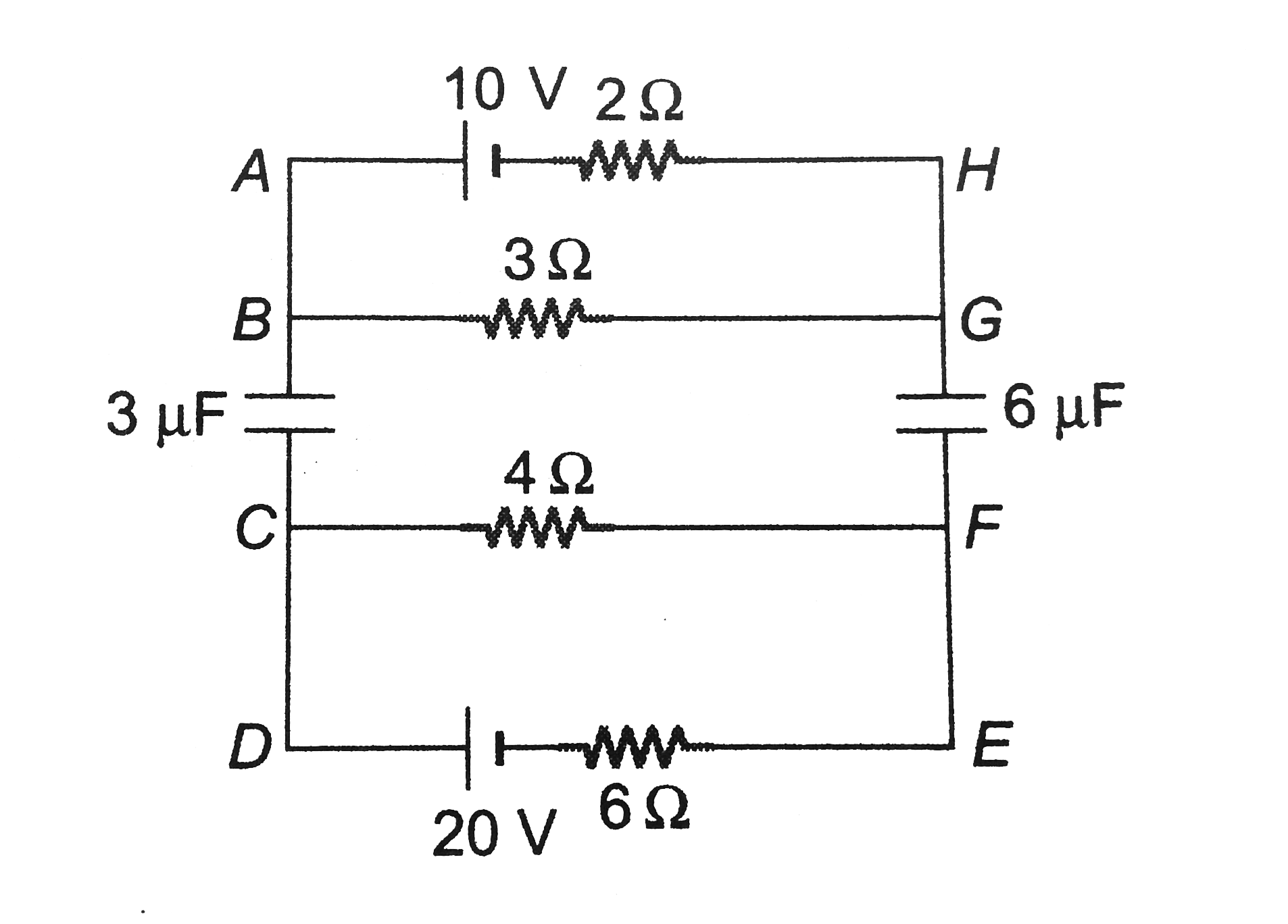
In the circuit shown in figure, find the steady state charges on oth the capacitors.
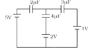
View SolutionIn steady state, find the charge on 3μF capacitor in μC
View SolutionConsider the circuit shwon in fig. The circuit is in steady state.
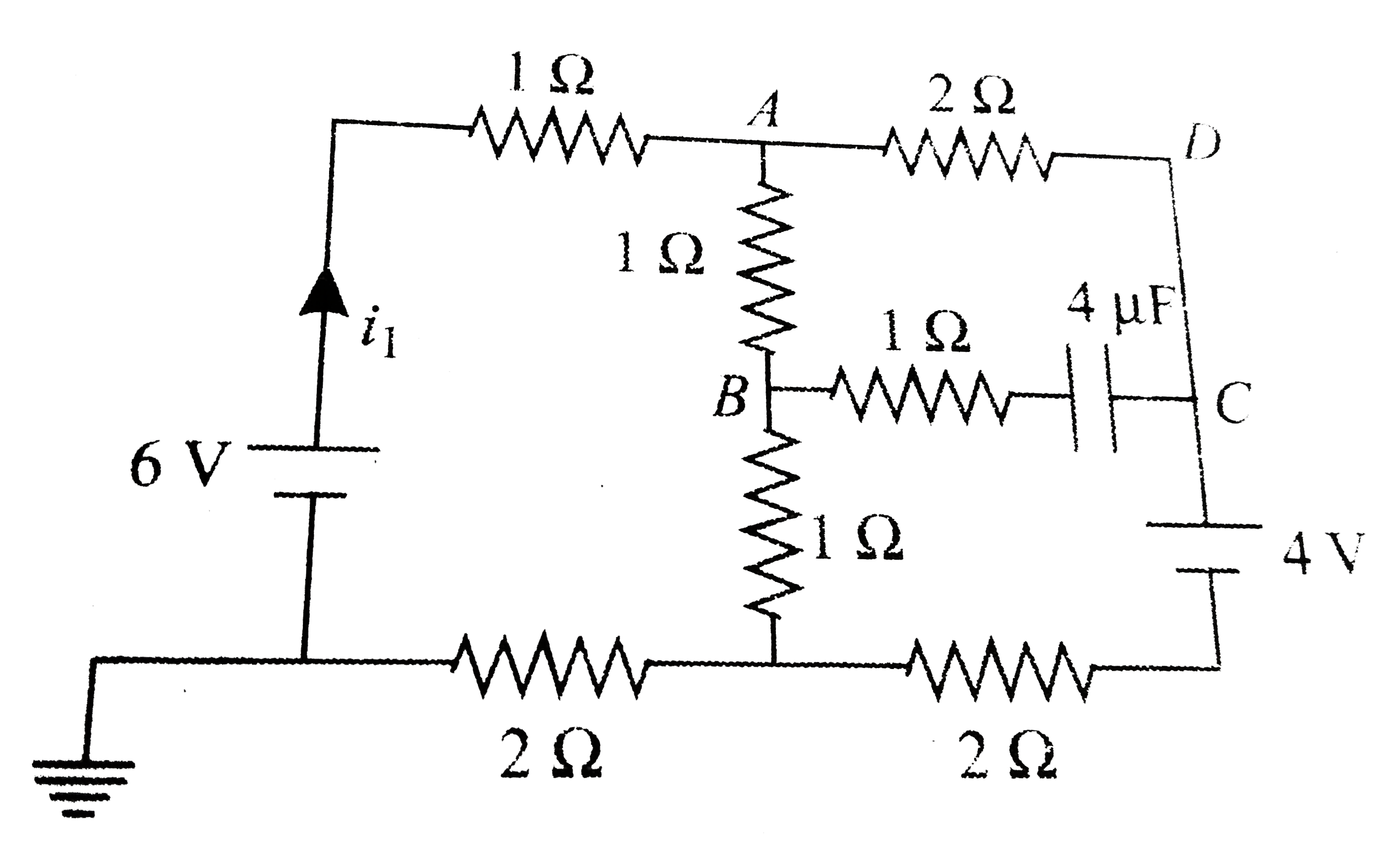
The charge in capacitor is
View SolutionIn the circuit shown in the figure, in steady state:
The current drawn from the battery is
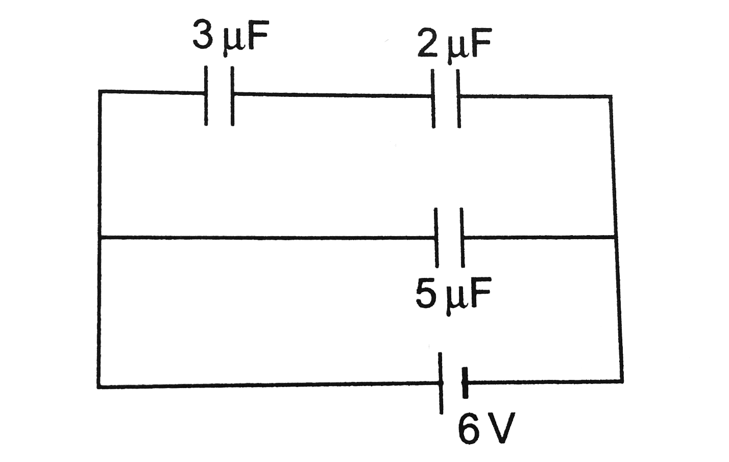
View SolutionIn the circuit shown in figure, the ratio of charge on 5μF and 2μF capacitor is
View SolutionThe circuit shown in fig 5.223 is in steady state.
find the charges on the capacitors C1andC2 respectively.
View Solution(a)Find the current I supplied by the battery in the network shown in figure in steady state. (b)find the charge on the capacitor.
View SolutionFor the circuit shown in the figure determine the charge on capacitor in steady state.
View SolutionFor the circuit shown in the figure, find the charge stored on capacitor in steady state.
View SolutionThe circuit is in a steady state.
The charge in capacitor C3 is
View Solution
