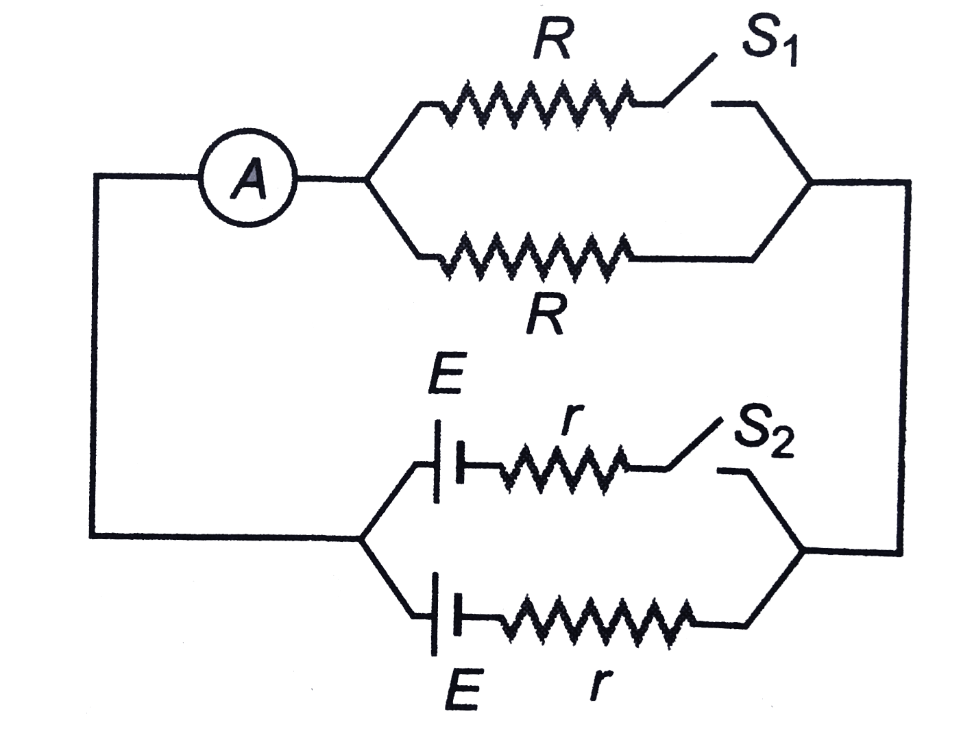
On closing the switch S in the circuit as shown in the figure, the reading of the galvanometer G 
Increases
Decreases
Remains same
May increase or decrease
Step by step video & image solution for On closing the switch S in the circuit as shown in the figure, the reading of the galvanometer G by Physics experts to help you in doubts & scoring excellent marks in Class 12 exams.
Updated on:21/07/2023Topper's Solved these Questions
- TEST 1BOOK - AAKASH INSTITUTE ENGLISHCHAPTER - TEST 1EXERCISE - EXERCISE
21 Videos
- SYSTEM OF PARTICLES AND ROTATIONAL MOTIONBOOK - AAKASH INSTITUTE ENGLISHCHAPTER - SYSTEM OF PARTICLES AND ROTATIONAL MOTIONEXERCISE - Try Yourself
63 Videos
- TEST 2BOOK - AAKASH INSTITUTE ENGLISHCHAPTER - TEST 2EXERCISE - Exercise
308 Videos
Similar Questions
Knowledge Check
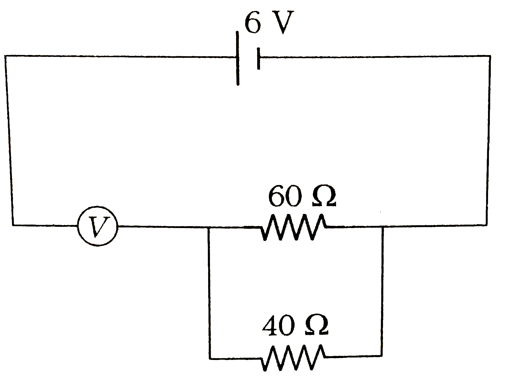
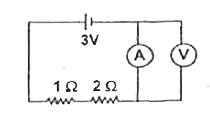
In the circuit shown in figure, what will be the reading of the voltmeter ?
 A300 VB900 VC200 VD400 V
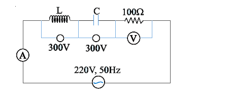
In the circuit shown in figure, what will be the readings of voltmeter and ammeter?
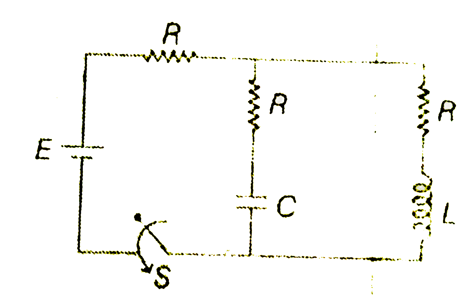
View SolutionIn the circuit as shown in the figure, switch S is added at t=0. Then:
View SolutionThe reading of ammeter in the circuit shown in the figure is
_PHY_E05_104_Q01.png)
View SolutionThe reading of ammeter in the circuit shown in the figure is
_PHY_E05_032_Q01.png)
View SolutionIs correct. In the circuit shown in the figure, the voltmeter reading would be.
View SolutionAfter switch is closed in the LC circuit shown in the figure, the charge on the capacitor is sometimes zero, but at such instants the current in the circuit is not zero. How is this behaviour possible ?

View SolutionIn a galvanometer 5% of the total current in the circuit passes through it. If the resistance of the galvanometer is G, the shunt resistance 'S' connected to the galvanometer is
View Solution

