The switch S has been closed for long time and the electric circuit shown caries a steady current. Let C1=3.0μF,C2=6.0μF,R1=4.0kΩ,andR1=7.0kΩ
The power dissipated in R2 is 2.8 W.
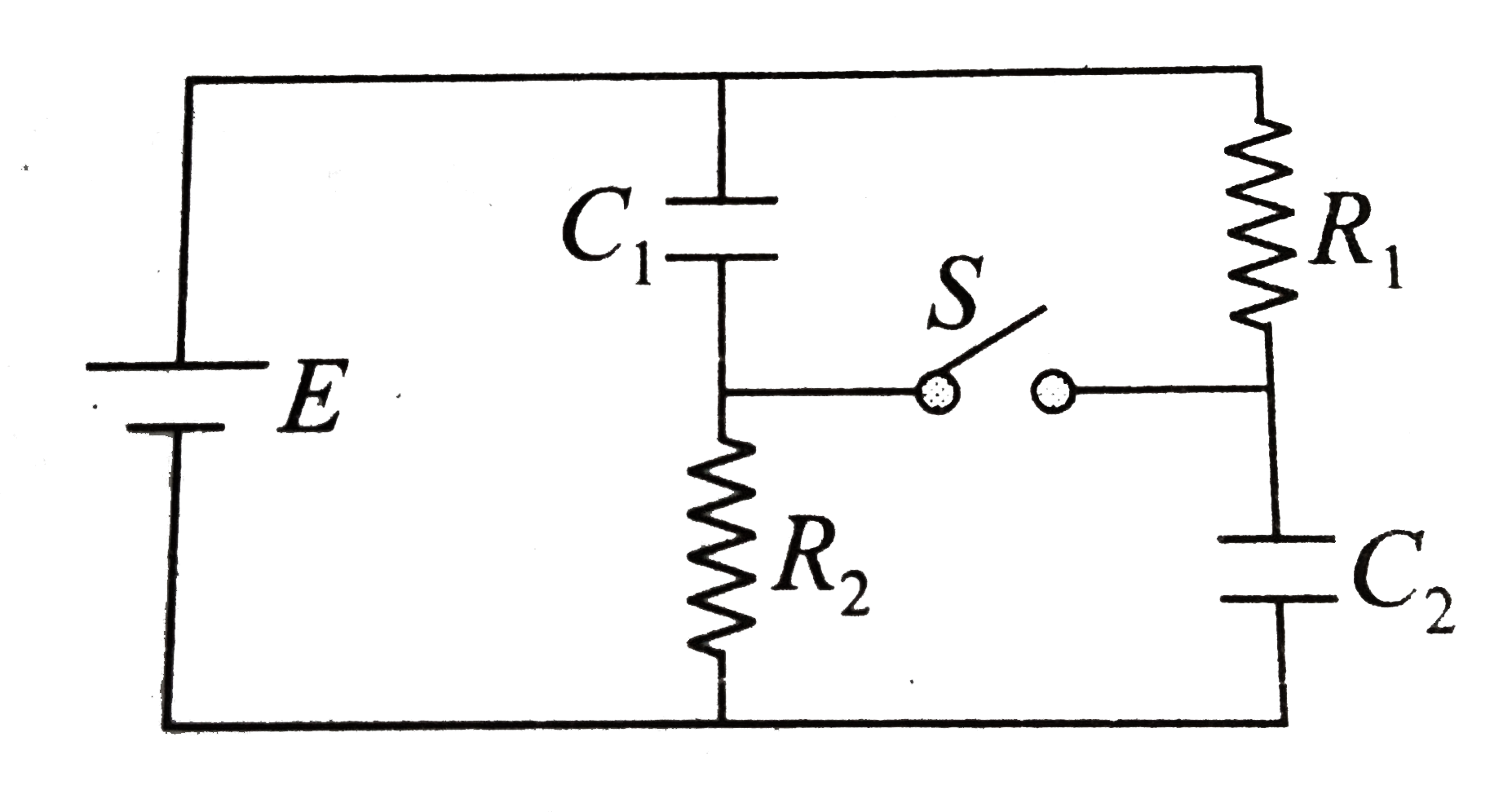
The power dissipated to the resistor R1is1.6W.
The charge on capacitor C1is240μC.
The charge on capacitor C2is440μC.
Long time after switch is opened, the charge on C1is660μC.
The correct Answer is:A, B, D
a., b., d.
i=2×10⁻²A
PR1=i2R1=(2×10⁻²)2×4×103=1.6W
QC1=VR1×C1=80×3×10−6=240μC
QC2=VR2×C2=140×6×10−6=840μC
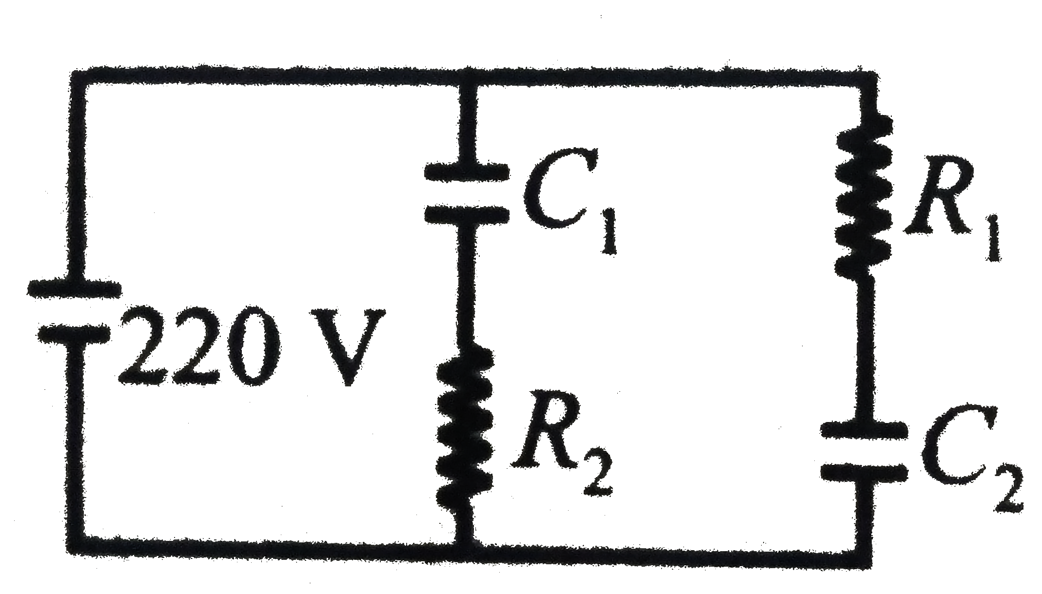
QC1=EC1=220×3×10−6=660μC
Topper's Solved these Questions
- MISCELLANEOUS VOLUME 3BOOK - CENGAGE PHYSICS ENGLISHCHAPTER - MISCELLANEOUS VOLUME 3EXERCISE - Assertion and Reason
8 Videos
- MISCELLANEOUS VOLUME 3BOOK - CENGAGE PHYSICS ENGLISHCHAPTER - MISCELLANEOUS VOLUME 3EXERCISE - Integer Answer Type
11 Videos
- MISCELLANEOUS VOLUME 3BOOK - CENGAGE PHYSICS ENGLISHCHAPTER - MISCELLANEOUS VOLUME 3EXERCISE - Assertion-Reasoning Type
1 Video
- MAGNETIC FIELD AND MAGNETIC FORCESBOOK - CENGAGE PHYSICS ENGLISHCHAPTER - MAGNETIC FIELD AND MAGNETIC FORCESEXERCISE - Multiple Correct Answer type
2 Videos
- MISCELLANEOUS VOLUME 5BOOK - CENGAGE PHYSICS ENGLISHCHAPTER - MISCELLANEOUS VOLUME 5EXERCISE - Integer
12 Videos
Similar Questions
In the circuit shown below E1=4.0V,R1=2Ω,E2=6.0V,R2=4Ω and R3=2Ω. The current I1 is
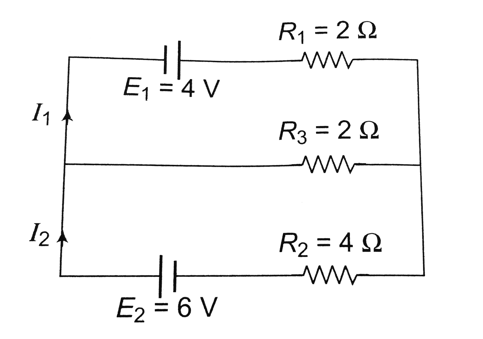
View SolutionIn the following circuit ,E1=4V,R1=2Ω,
E2=6V,R2=2Ω,andR3=4Ω. Find the currents i1andi2
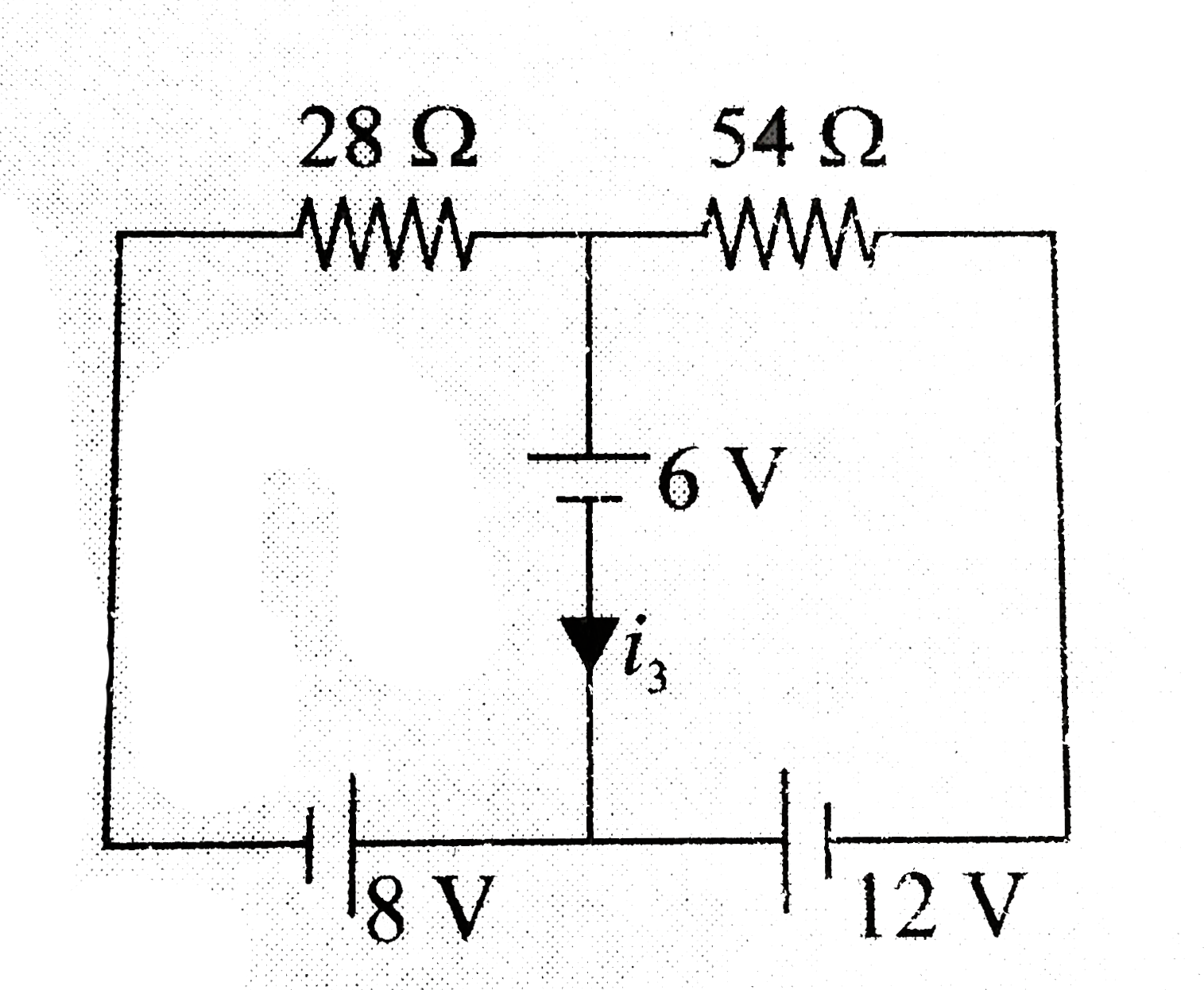
View SolutionSwitch is closed at t=0 then the current in the circuit at t=L2R is
_PHY_E06_157_Q01.png)
View SolutionAn LR circuit having L=4.0H,R=1.0Ωandε=6.0V is switched on at t=0. find the power dissipated in joule heating at t=4.0s.
View SolutionIn a series RC circuit with an AC source, R=300Ω,C=25μF,ε0=50V and v=50πHz. Find the peak current and the average power dissipated in the circuit.
View SolutionIn the circuit shown, E1=7V,E2=7V,R1=R2=1Ω and R3=3Ω respectively. The current through the resistance R3
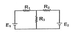
View SolutionIn the circuit shown, E1=7V,E2=7V,R1=R2=1Ω and R3=3Ω respectively. The current through the resistance R3

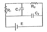
View SolutionIn the circuit shown in figure, R(1)=1Ω,R2=2Ω,C1=1μF,C2=2μF and E=6V. Calculate charge on each capacitor in steady state
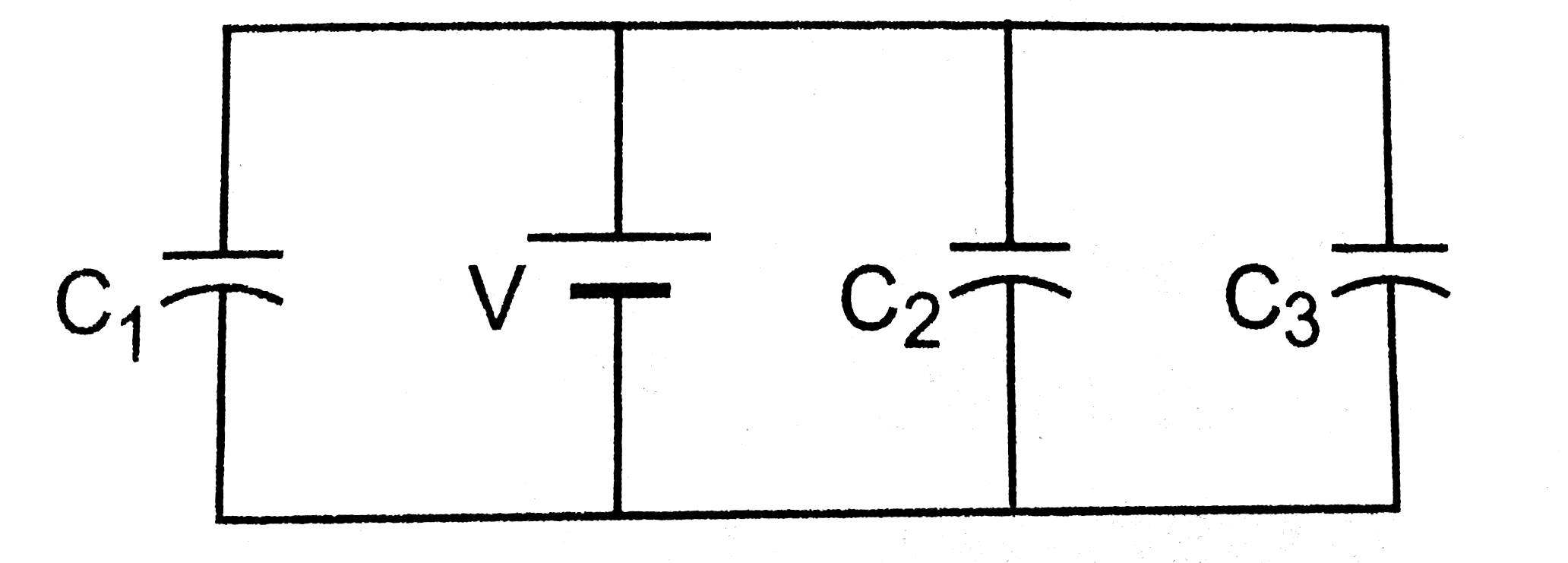
View SolutionFind the charges on the three capacitors connected to a bettery as shown in figure (31.E1). Take C_1=2.0,muF, C_2=4.0,muf, C_3=6.0,muF and V=12 volts.
View SolutionPassage :
Suppose the switch S has been sufficiently long time for the capacitor to become fully charged. Find (where R1=12kΩ,R2=15kΩ,R3=5kΩ)

The steady-state current through each resistor
View Solution