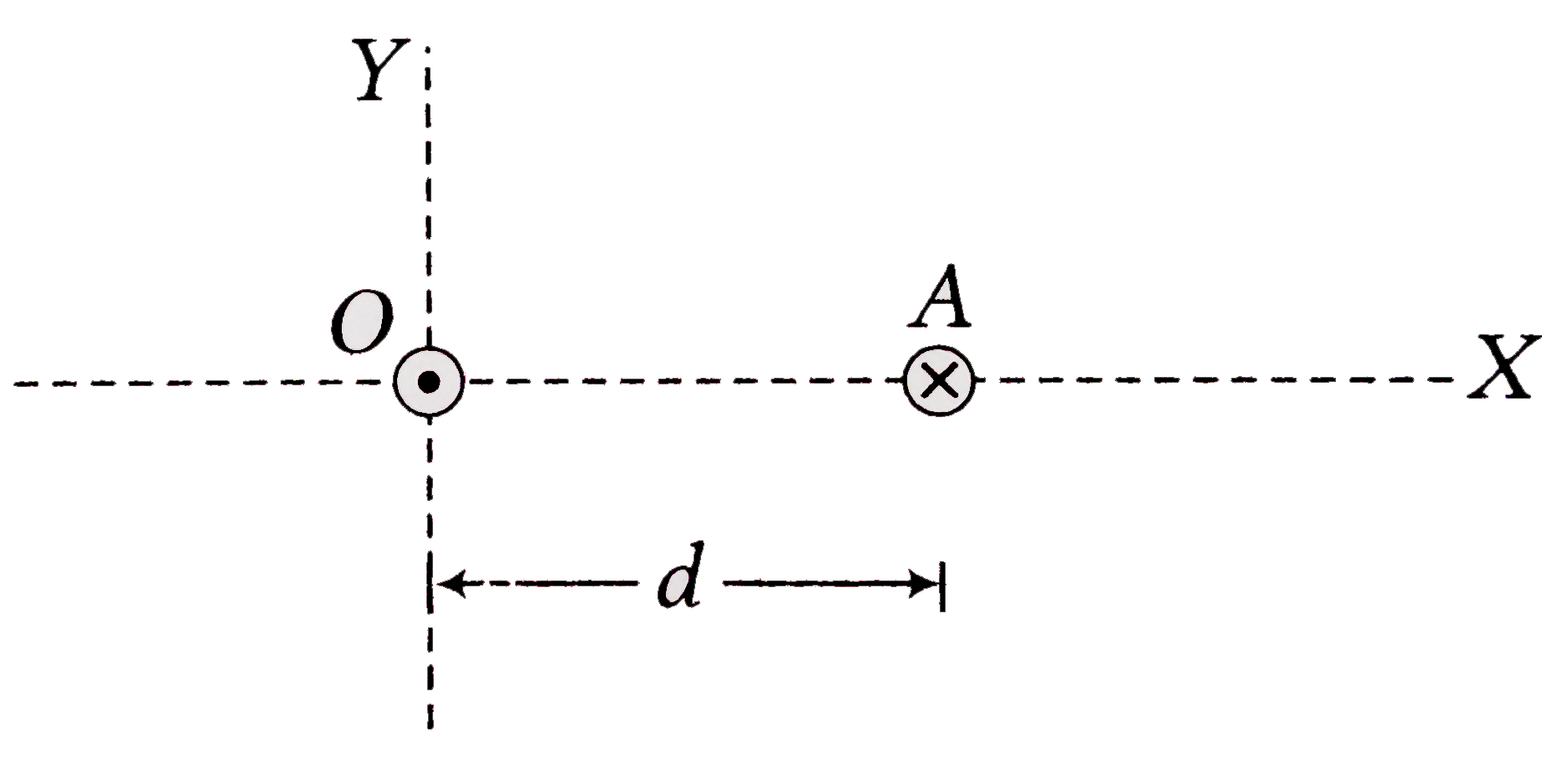
Two long parallel wires are at a distance 2d apart. They carry steady equal currents flowing out of the plane of the paper , as shown. The variation of the magnetic field B along the line XX is given by
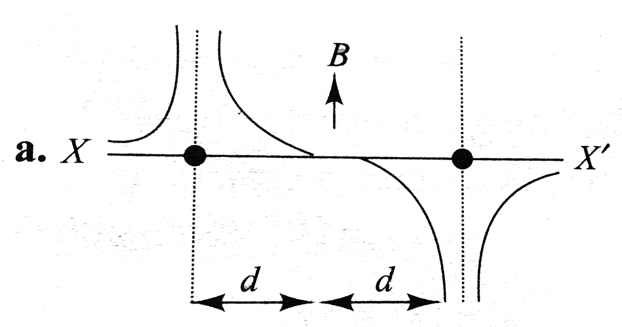
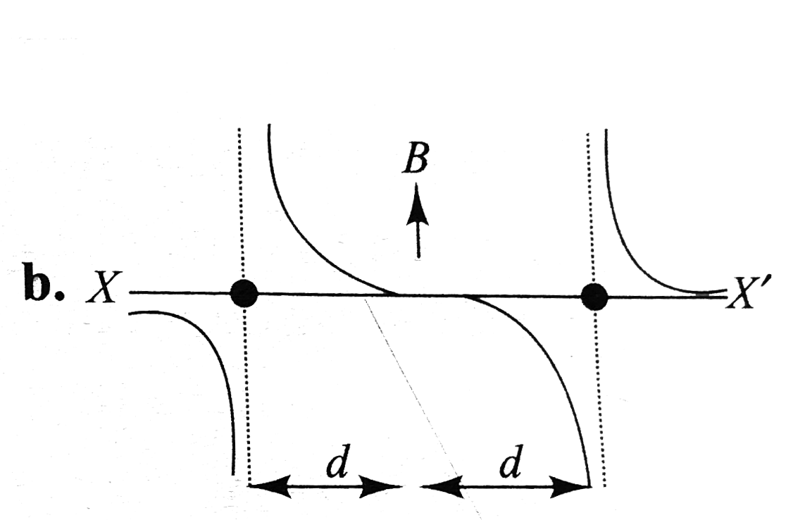
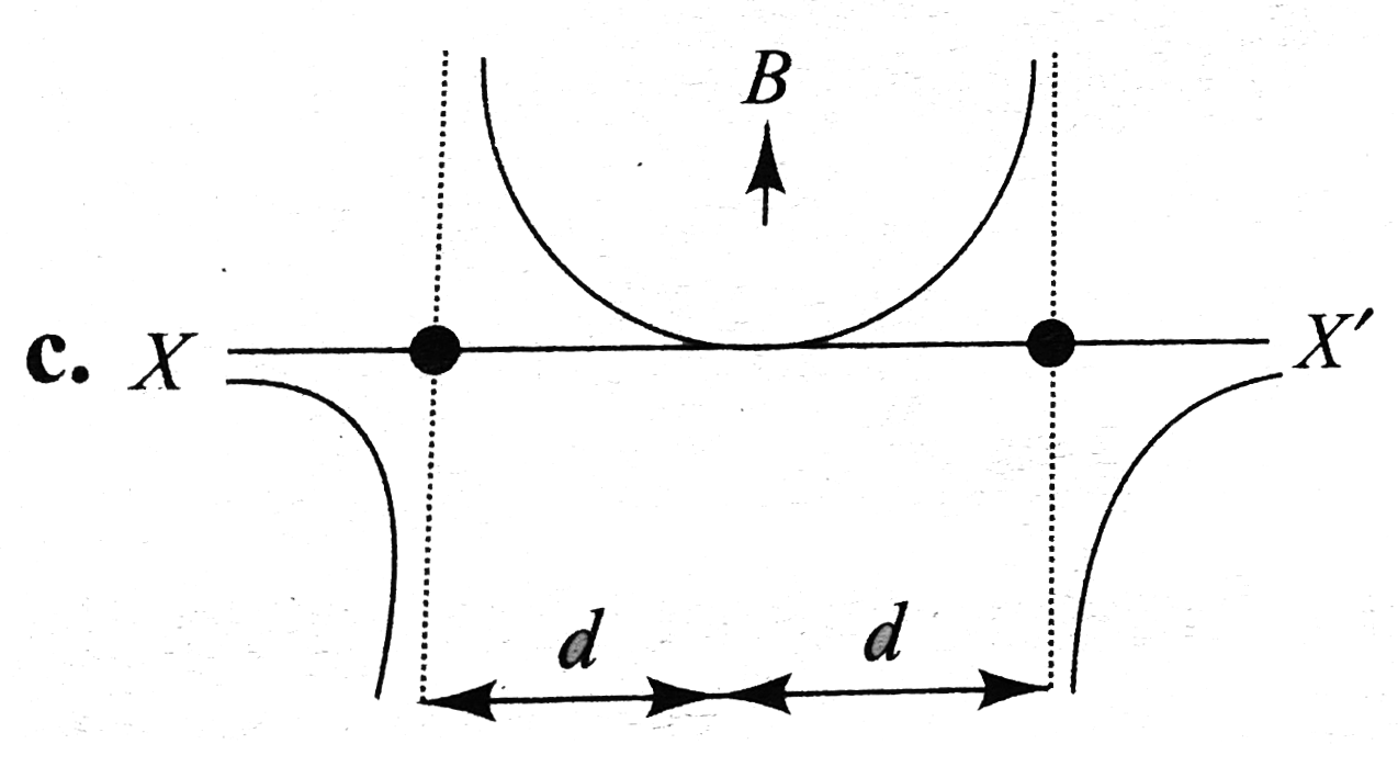
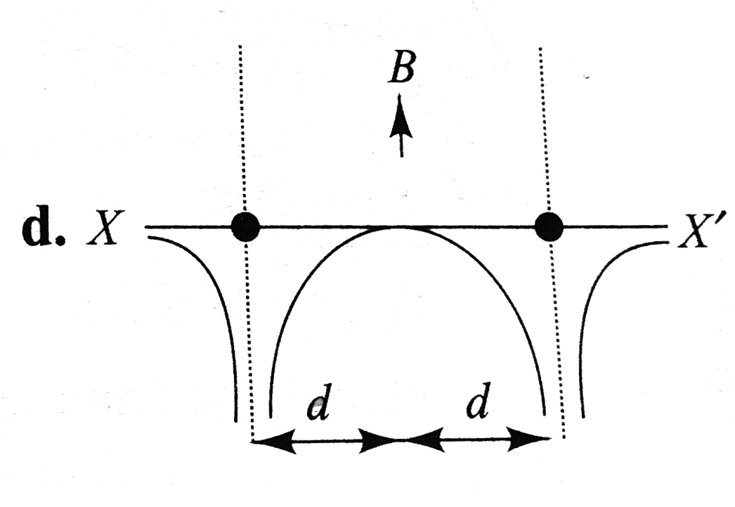
The correct Answer is:B
To solve the problem of finding the variation of the magnetic field B along the line XX due to two long parallel wires carrying equal currents, we can follow these steps:
Step 1: Understand the Setup
We have two long parallel wires separated by a distance of 2d, with both wires carrying equal currents flowing out of the plane of the paper. We need to analyze the magnetic field at various points along the line XX.
Step 2: Define the Position
Let’s denote the left wire as wire 1 and the right wire as wire 2. We can define a point P located at a distance x from wire 1. Consequently, the distance from wire 2 to point P will be 2d−x.
Step 3: Calculate the Magnetic Field from Each Wire
Using the formula for the magnetic field B due to a long straight wire, we have:
B1=μ0I2πx(magnetic field due to wire 1)
B2=μ0I2π(2d−x)(magnetic field due to wire 2)
Step 4: Determine the Directions of the Magnetic Fields
Using the right-hand rule:
- For wire 1 (left wire), the magnetic field B1 at point P will be directed upwards (positive j-direction).
- For wire 2 (right wire), the magnetic field B2 at point P will be directed downwards (negative j-direction).
Step 5: Write the Net Magnetic Field
The net magnetic field Bnet at point P can be expressed as:
Bnet=B1−B2=μ0I2πx−μ0I2π(2d−x)
Step 6: Simplify the Expression
Factoring out the common terms:
Bnet=μ0I2π(1x−12d−x)
Step 7: Analyze Special Cases
1. At x=d:
Bnet=μ0I2π(1d−1d)=0
The magnetic field is zero at the midpoint between the two wires.
2. For x<d:
The term 1x dominates, making Bnet>0 (upward direction).
3. For x>d:
The term 12d−x dominates, making Bnet<0 (downward direction).
Step 8: Conclusion
The variation of the magnetic field B along the line XX can be summarized as:
- B>0 for x<d (upward)
- B=0 for x=d
- B<0 for x>d (downward)
We have two long parallel wires separated by a distance of 2d, with both wires carrying equal currents flowing out of the plane of the paper. We need to analyze the magnetic field at various points along the line XX.
Let’s denote the left wire as wire 1 and the right wire as wire 2. We can define a point P located at a distance x from wire 1. Consequently, the distance from wire 2 to point P will be 2d−x.
Using the formula for the magnetic field B due to a long straight wire, we have:
B1=μ0I2πx(magnetic field due to wire 1)
B2=μ0I2π(2d−x)(magnetic field due to wire 2)
Using the right-hand rule:
- For wire 1 (left wire), the magnetic field B1 at point P will be directed upwards (positive j-direction).
- For wire 2 (right wire), the magnetic field B2 at point P will be directed downwards (negative j-direction).
The net magnetic field Bnet at point P can be expressed as:
Bnet=B1−B2=μ0I2πx−μ0I2π(2d−x)
Factoring out the common terms:
Bnet=μ0I2π(1x−12d−x)
1. At x=d:
Bnet=μ0I2π(1d−1d)=0
The magnetic field is zero at the midpoint between the two wires.
The term 1x dominates, making Bnet>0 (upward direction).
The term 12d−x dominates, making Bnet<0 (downward direction).
The variation of the magnetic field B along the line XX can be summarized as:
- B>0 for x<d (upward)
- B=0 for x=d
- B<0 for x>d (downward)
Topper's Solved these Questions
- SOURCES OF MAGNETIC FIELDBOOK - CENGAGE PHYSICS ENGLISHCHAPTER - SOURCES OF MAGNETIC FIELDEXERCISE - Archives (multiple Correct )
1 Video
- SOURCES OF MAGNETIC FIELDBOOK - CENGAGE PHYSICS ENGLISHCHAPTER - SOURCES OF MAGNETIC FIELDEXERCISE - Archives (linked Comprehension)
4 Videos
- SOURCES OF MAGNETIC FIELDBOOK - CENGAGE PHYSICS ENGLISHCHAPTER - SOURCES OF MAGNETIC FIELDEXERCISE - Archives (fill In The Blanks)
1 Video
- RAY OPTICSBOOK - CENGAGE PHYSICS ENGLISHCHAPTER - RAY OPTICSEXERCISE - DPP 1.6
12 Videos
- WAVE OPTICSBOOK - CENGAGE PHYSICS ENGLISHCHAPTER - WAVE OPTICSEXERCISE - Comprehension Type
14 Videos
Similar Questions
Two long, straight, parallel wires are 1.00m apart (as shown in Fig). The upper wire carries a current I1 of 6.00A into the plane of the paper.
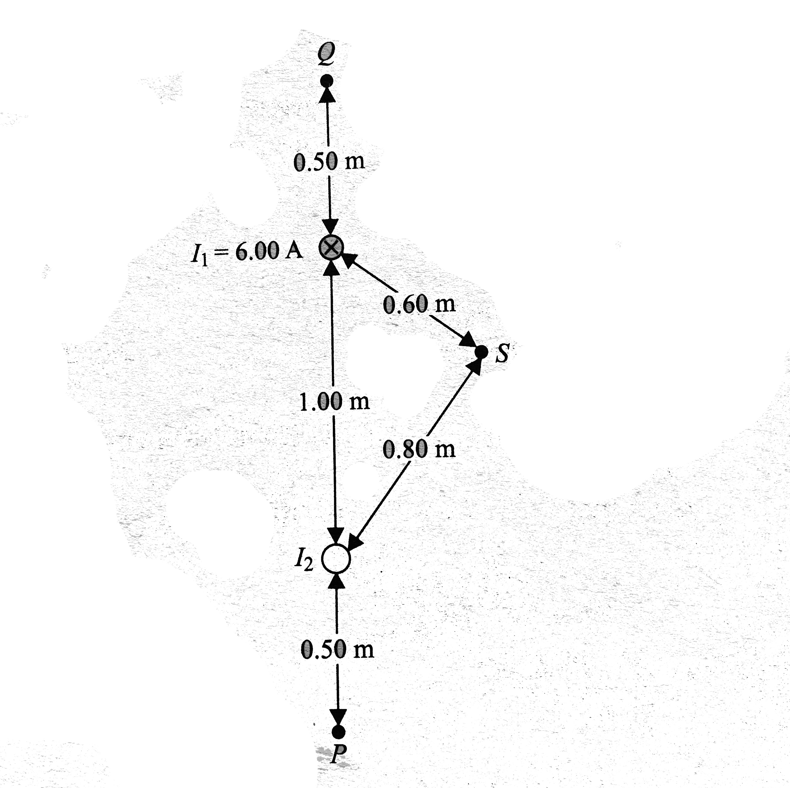
What is the magnitude of the net field at Q?
View SolutionTwo long, straight, parallel wires are 1.00m apart (as shown in Fig). The upper wire carries a current I1 of 6.00A into the plane of the paper.
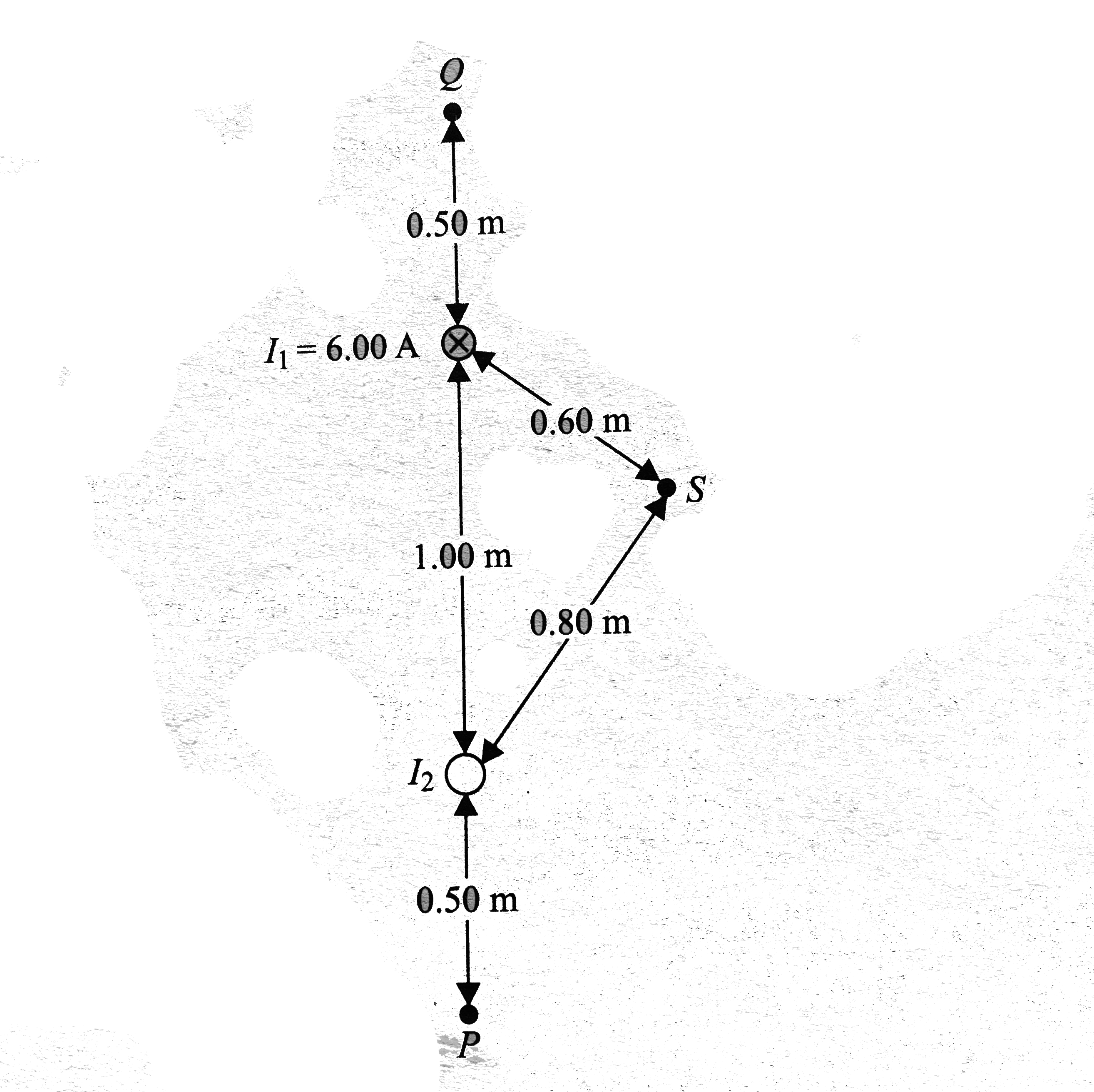
What is the magnitude of the net field at S?
View SolutionTwo thin, long, parallel wires, separated by a distance 'd' carry a current of 'i' A in the same direction. They will
View SolutionLet two long parallel wires, a distance d apart, carry equal currents I in the same direction. One wires at x=0, the other at x=d (as shown in Fig) Determine magnetic field at any point x-axis between the wires as a function of x.

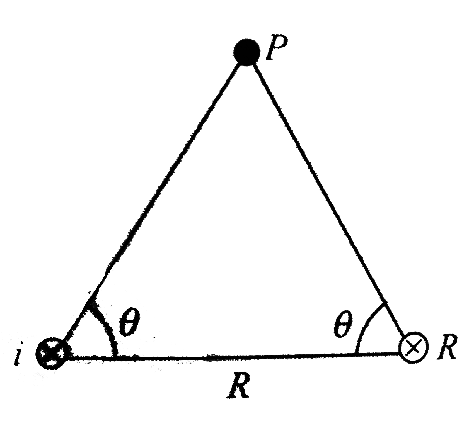
View SolutionIn Fig. two long parallel wires (seen end-on) that are a distance R apart carry equal currents i in the same sense. Find the magnitude of the magnetic field at point P , which lies quidistant from the two wires at an angle θ from the plane of the wires.
View SolutionTwo thin long wires are parallel to each other at a separation d apart and they carry equal currents l each along the same direction as shown in figure. The magnetic field (B) at a point P varieswith x according to graph.
_PHY_E06_274_Q01.png)
View SolutionTwo long conductors are arranged as shown above to form overlapping cylinders, each of radius r, whose centers are separated by a distance d. Current of density J flows into the plane of the page along the shaded part of one conductor and an equal current flows out of the plane of the page along the shaded portion of the other, as shown. What are the magnitude and direction of the magnetic field at point A? :

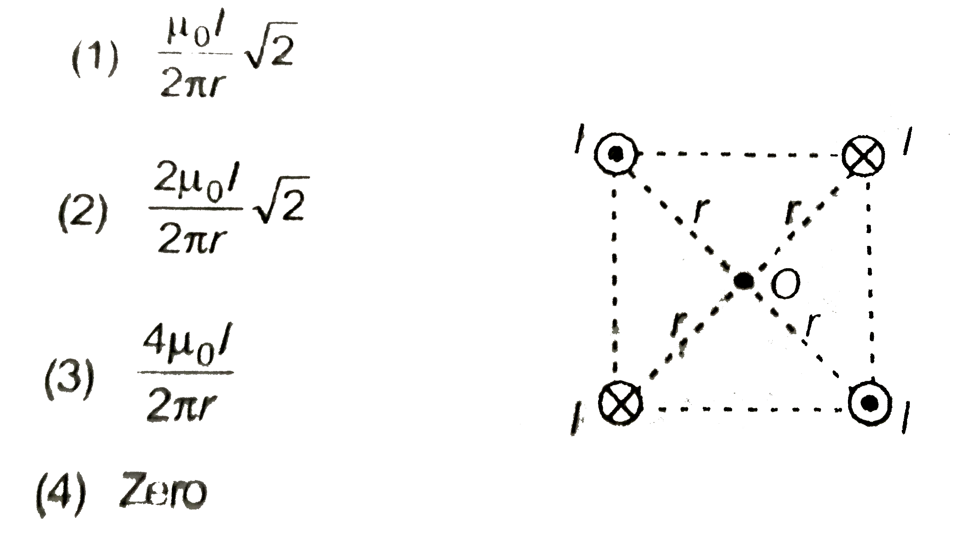
View SolutionFigure shows an arrangement in which long parallel wires carrying equal currents into or out of the page of paper at the corners of a square. The magnetic field at the centre of square is
View SolutionTwo long wires carrying same currents in opposite directions are placed at separation D as shown.Predict variation of magnetic field as one moves from the point O and A
View SolutionA current carrying wire AB of the length L is turned along a circle, as shown in figure. The magnetic field at the centre O.
View Solution